StrEng007
Structural
- Aug 22, 2014
- 526
This post is a follow-up to this thread:
 www.eng-tips.com
I'd like to treat this 2 part diaphragm as a single diaphragm, where the shears at each side of the boundary party wall cancel each other out. In order to do so, I need to make sure I get the shears into the party wall to create the location in which I can cancel out the shear demand at that interface.
How do I determine the forces at this location? Wouldn't it be the same as the shear flow for the chord force using the overall building length?
Putting some numbers to it:
Transverse Load = 100 lb/ft
B = 50 FT
L = 30 FT
Chord force = (100 lb/ft) (50 FT)²/(8x 30FT) = 1041.67 lb
Shear, V = (100 lb) x (50 FT)(1/2) = 2500 lb
Unit shear, v = 2500 lb/30 FT = 83.33 lb/ft
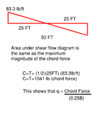
Note, unit shear is same as shear flow of the chord = Chord/(0.25B) = 83.33 lb/ft
That is, if you take the total area under the shear flow linear distribution, you get the chord force in the overall diaphragm.

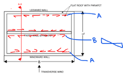
So is this to say that the shear located on each side of the party wall is 83.33 lb/ft as shown below?
That would keep equal and opposite forces in equilibrium when considering each half of the diaphragm.
If not, what is the shear demand each side of the party wall at B?

Simple diaphragm with interior wall interruption - Structural engineering general discussion
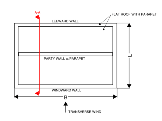
What happens to the chord forces in a flexible roof diaphragm when an interior partition wall interrupts the diaphragm? Is the chord force still wB2/8L for the windward and leeward walls only (see diagrams)? Or, are there now two sub diaphragms, one for the windward side of the building and...
I'd like to treat this 2 part diaphragm as a single diaphragm, where the shears at each side of the boundary party wall cancel each other out. In order to do so, I need to make sure I get the shears into the party wall to create the location in which I can cancel out the shear demand at that interface.
How do I determine the forces at this location? Wouldn't it be the same as the shear flow for the chord force using the overall building length?
Putting some numbers to it:
Transverse Load = 100 lb/ft
B = 50 FT
L = 30 FT
Chord force = (100 lb/ft) (50 FT)²/(8x 30FT) = 1041.67 lb
Shear, V = (100 lb) x (50 FT)(1/2) = 2500 lb
Unit shear, v = 2500 lb/30 FT = 83.33 lb/ft
Note, unit shear is same as shear flow of the chord = Chord/(0.25B) = 83.33 lb/ft
That is, if you take the total area under the shear flow linear distribution, you get the chord force in the overall diaphragm.

So is this to say that the shear located on each side of the party wall is 83.33 lb/ft as shown below?
That would keep equal and opposite forces in equilibrium when considering each half of the diaphragm.
If not, what is the shear demand each side of the party wall at B?


