Continue to Site

Eng-Tips is the largest engineering community on the Internet

Intelligent Work Forums for Engineering Professionals

  • Congratulations KootK on being selected by the Eng-Tips community for having the most helpful posts in the forums last week. Way to Go!

Simple for DL but contionous for LL - negative moment 1

Status
Not open for further replies.

mar2805

Structural
Dec 21, 2008
372
Hello!
Can you please look at the picture attached.
I have and series of T beam over wich an RC slab will be poured.

When designing for an negative moment over the support, wich of the 3 geometry cases is valid for design:

1) TOP one, the whole structure is behaving as one body - T beam and decks act as one body. reinforcement will be placed in the top layer of the slab

2.) MIDDLE one, using only T section for determining flexural reinforcement wich will be placed in RC slab in top layer

3.) BOTTOM one, using only slab portion of the geometry for determinng flexural reinforcement wich will be placed in top layer of the slab

Basicly first two statements are the same since the neutral axis is always going to be under the flange BUT there is an difference in height of the section!
 
 https://files.engineering.com/getfile.aspx?folder=60c14e4b-dc81-41b6-8e66-066d34382629&file=slab_deck.jpg
Replies continue below

Recommended for you

Probably 1 or 3 depending on how you connect the T beams across the support. But maybe something else because the slab and T neutral axes are at different levels. Can't say yet from this information.
 
Option 1 is valid if you can justify the lateral shear transfer between the T Beam and the topping slab.

Option 2 is wrong, you are considering only the T Beam as the flexural element and then place the reinforcement on the topping slab which is like placing a slab top reinforcement in a floor screed and expecting the slab to work.

I don't see why one would consider Option 3. If the slab is the only flexural element then there is no need for a T beam under it.
 
Option 1 seems like a npormal solution to me to.
We will check the lateral shear across the contact surface ( top flange of T beam and bottom face of the slab) and design stirups that will hold the "2 bodies together".
 
@steveh49

depending on how you connect the T beams across the support

What scenarios did you had in mind. We use a standard 90degress hook that come from the beam bottom end wich is embeded in RC diaphragm part of the support
 
I think hetgen has it right on. If you have reinforcing crossing the interface between the T section and the slab, it has to be adequate to transfer the shear across the joint, both for fatigue and ultimate strength. If it's adequate for those 2 load cases, it's a composite section. If the concrete strengths in the slab and T section are similar, the flaxural strength can be calculated as if it's a monolithic section (subject to the interface shear capacity being adequate, as mentioned above).

If you don't have reinforcing crossing the interface, it's not continuous; you have simple spans.
 
When you say T-beams, do you mean precast double tees or cast-in-place T-beams?
 
Btw, if you're making it composite, as discussed, you can use both the top and bottom layers of deck reinforcement as tension reinforcement.
 
Also, are the T sections prestressed? Are they bulb tee sections? What size? What are the spans?
 
you can use both the top and bottom layers of deck reinforcement as tension reinforcement.

This is an usefull information.
But when designing for negative moment I would have to use lever arm that in the centroid of the two reinforcement layers, correct?
 
If it's a composite section, with a concrete between the ends of the stems of the T sections, giving you continuity of the compression zone, it becomes one section, as you have it shown in case 1 in your attached sketch. Everything above the neutral axis is in tension - all the reinforcing in the slab, and the reinforcing in the flange of the tee.

It gets a little tricky as to whether you can count reinforcing that is close to the neutral axis (less than 20% of the distance to the outermost reinforcement layer), but unless the stem width is tiny, the neutral axis should be near the bottom of the stem, so you shouldn't have any problem using at least the slab and flange reinforcement.
 
HotRod10, EXCELENT comment/advice!
Thank you!
 
A caution, since you did not answer my query of whether the girders are prestressed or not: If they are prestressed, the analysis gets very complex. Concrete creep, and other prestress losses over time, will change the stresses in the slab from it's initial condition. If this is the case, I'd advise involving someone experienced with prestressed concrete design to help you through the analysis.
 
mar2805 said:
What scenarios did you had in mind. We use a standard 90degress hook that come from the beam bottom end wich is embeded in RC diaphragm part of the support

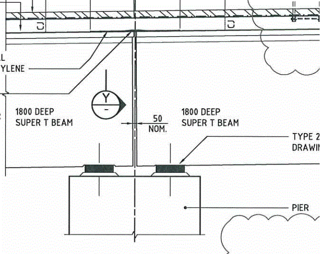
Bridge deck slabs are often continuous over a pier but the precast girders are not otherwise connected. This is to improve the 'ride' for vehicles using the bridge rather than for structural reasons. See the 50mm gap in the image below. Sometimes the gap is made significantly larger so the slab flexes about its own axis.

hinge_slab_rgt3rj.gif
 
"Bridge deck slabs are often continuous over a pier but the precast girders are not otherwise connected."

In that situation, the girders are not continuous for live load (as the title of the thread states), nor any loads at all. What you depict is simple spans.
 
HotRod10 said:
In that situation, the girders are not continuous for live load (as the title of the thread states), nor any loads at all. What you depict is simple spans.

I don't see 'girders' in the thread title. The first post refers to a slab poured 'over' the girders and Option 3 suggested that might be all there is. It turns out that's not the case, but Options 1 & 3 are so different I wasn't sure the long-section details had been considered yet; perhaps only the cross-section.
 
"I don't see 'girders' in the thread title."

I was referring to the "...continuous for LL..." part of the title. Having only the slab 'continuous' provides negligible continuity to the superstructure.

"Options 1 & 3 are so different I wasn't sure the long-section details had been considered yet; perhaps only the cross-section."

A good addition to the discussion. I just wanted to be sure the OP recognizes that what you detailed is Option 3, and there's effectively no continuity of the superstructure with that option.
 
Sorry for the delay.
No, the T beams are not prestressed!
And yes we are going for the continuity over the supports using the rc slab thats going to be poured over the T beams flanges.
 
So long as you have adequate reinforcing crossing the interface between the T sections and the slab that is cast in on both sides, and you provide for adequate compression transfer at the bottom between the ends of the beams, it should be feasible.

Refer to the interface shear friction provisions of the bridge design spec you're using for design to determine the adequate area of reinforcing crossing the interface.
 
Status
Not open for further replies.

Part and Inventory Search

Sponsor