Eng-Tips is the largest engineering community on the Internet

Intelligent Work Forums for Engineering Professionals

Simple Modelling of Wall Support Conditions

Status
Not open for further replies.

Redacted

Structural
Mar 12, 2016
160
0
0
BM
Hi there,

I'm working on the design of supports for a transfer beam that is carrying two storeys above. The loads are quite large, so I am trying to see if there are ways that I can be a bit less conservative with the analysis model.

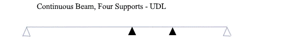
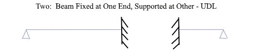
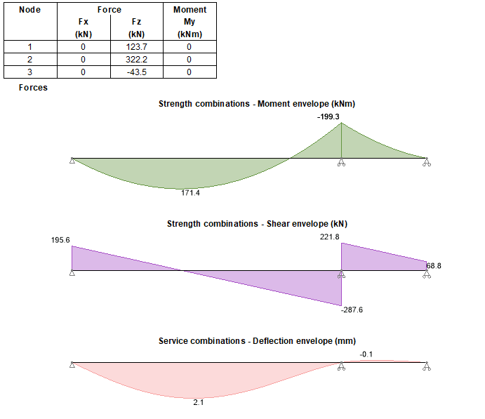
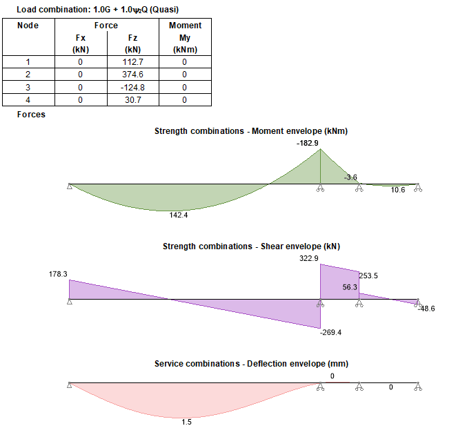
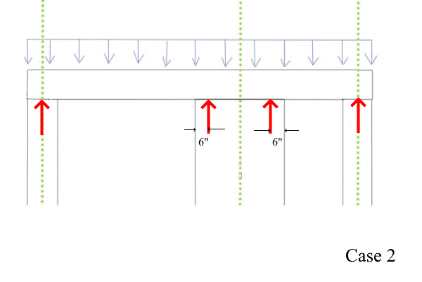
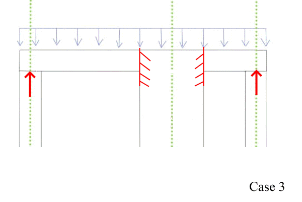
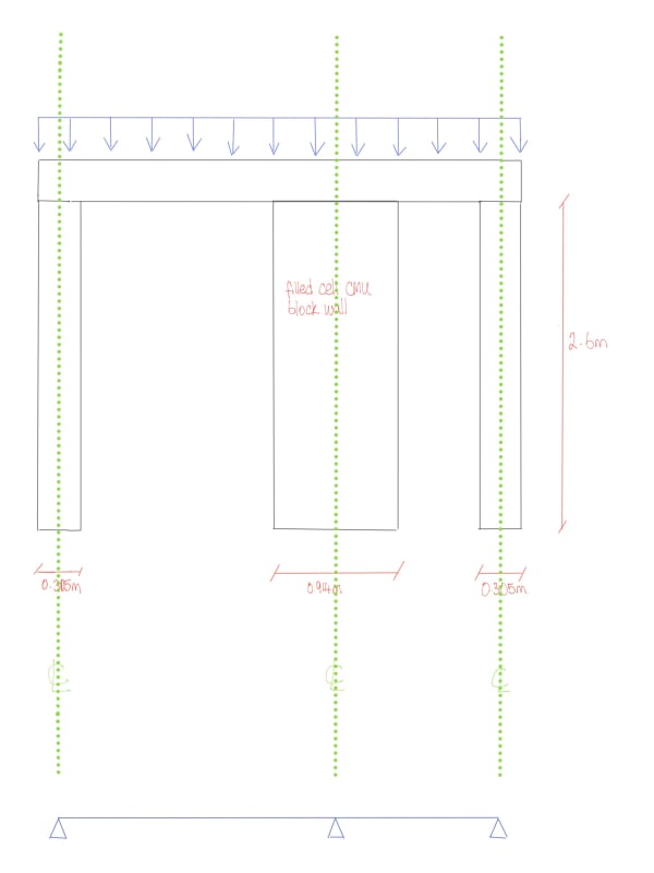
How should I be analysing a structure with a continuous support that is quite long (3' or 0.914m)?

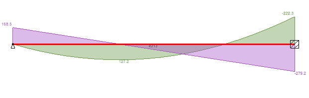
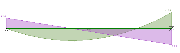
Analysing the structure with the support directly in the center may be too conservative, as it would be increasing the clear span of the transfer beam (increasing the overall loads on the supports). Should I also be putting a support at the start of the 0.914m wall and at the end of the 0.914, wall (effectively putting in 3 supports for that mid wall?). What is best practice in a situation like this?

New_Drawing_61_-_Copy_aupswe.jpg


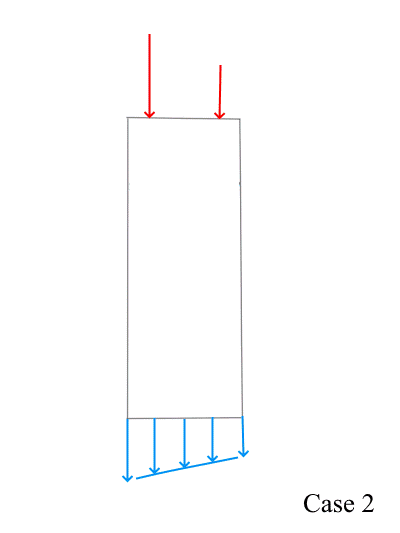
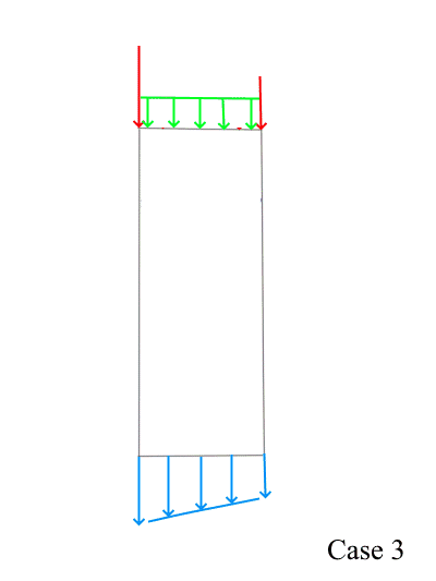
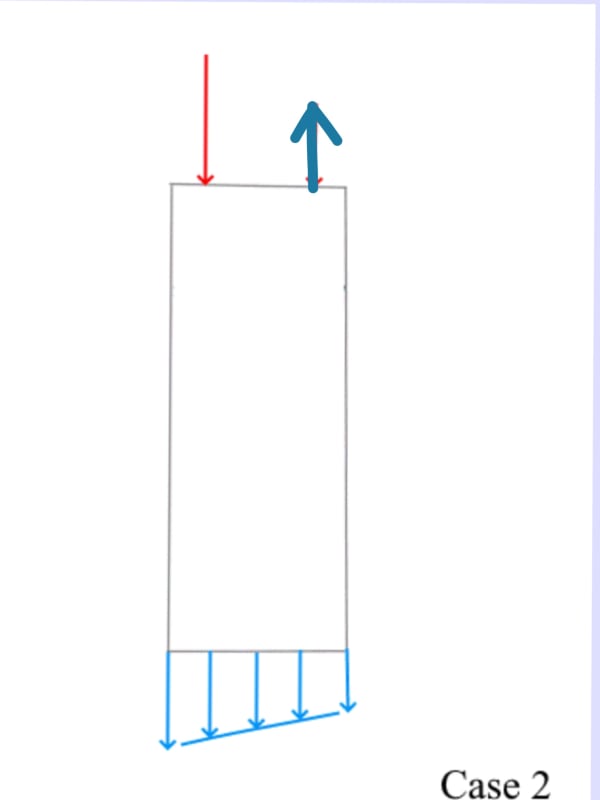
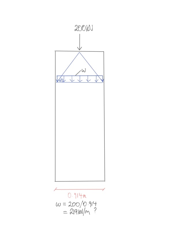
Also - I need to determine the UDL on the footing from the top point load reaction on the wall, so that the strip footing can be designed. Is what is shown in the sketch below the correct approach to calculating the footing UDL from the point load?

New_Drawing_61_1_-_Copy_jukfx2.jpg
 
Replies continue below

Recommended for you

I would want to get an idea of how conservative the "traditional" three-support assumption really is.
To do this, calculate three ways:

1) Continuous beam, three supports.

As you have shown.​

2) Continuous beam, four supports. Middle supports located in 6" from the edge.

Continuous-600_vvhmkv.png


3) Two each, beams fixed at one end, supported at the other.

Fixed-Supported-600_i8crtg.png


Next step depends on how tightly grouped are the answers.


For the footing: Load on the column might be eccentric instead of in the center. Us the results of Steps 2 & 3 (above) to determine possible eccentricity.
 
Why not model the entire structure? You could use shell elements for walls. In Eurocode 2, you have clear answers regarding your questions (I don't remember the answer by heart, but the code indicates how to take the clear span of beams supported on walls and other elements).
 
@ SRE

Thanks for the response, I appreciate your advice as always - please see the output results below :

1)
First_Support_Case_-_Copy_ciin3v.png


2)
Second_Support_Case_-_Copy_jk8ij3.png


3)
Third_Support_Case_1_-_Copy_qyyluk.png


Third_Support_Case_2_-_Copy_w1t9v1.png


@brTCP Thanks that is helpful, I'll try to find that documentation in the EuroCode. As for creating a full model, I'm not experienced enough with using modelling software packages, where I would feel confident enough to use the outputs from the model. Although it is something I am actively trying to learn (general FEA modelling best practice and SAP2000 etc). For now, I'm just seeing if I can get a reasonable approximation so that I can design the supporting walls and footings.
 
Redacted - Reading the OP, it's not clear to me what you want to accomplish. Is the goal to:

Reduce bending moment?
Then compare just the moment curves. Putting them all on one graph will make it easier to interpret the results.

Reduce deflection?
Compare just the deflection curves, all on one graph.

Redistribute load more equally among the three supporting columns?
That is likely not practical for a continuous beam (about 5/8 wl on the center support, no matter what assumptions are used).
Two simple beams will redistribute load (about 1/2 wl on the center support).


Hi SRE,

I guess it's a few things.

It would be nice to reduce bending moments in the beam if possible and it looks like the option 2 support conditions will allow me to achieve that.

I was hopeful about your 3rd point but as you mentioned likely not possible. For context, there's an existing foundation under that wall 30" wide and 15" deep, and I need to check if that has the capacity to take the loads from the new transfer beam or if it needs to be strengthened/increased in size.

However, I'm mainly trying to figure out how the load from the beam translates into the middle wall and how I can convert that into a line load on the strip footing. Should I be considering it as a point load and have that distribute at a 45 degree angle? Like the 2nd image in the original post?

 
Redacted - Very good, need to evaluate load distribution on the existing footing.

IMHO, both Case 2 and Case 3 are reasonable ways to (simply) model the continuous beam. The "best" answer is probably somewhere inbetween the two cases. For the given conditions, both cases will likely put a distributed load on the center footing... but it will not be uniform.

Consider Case 2:

Case_2_tzoefz.png


Loads on the two center supports are not equal. This means eccentric loading on the the center "column". The two point loads (shown in red) will distribute quickly over the length of the "column", but the eccentricity remains and is applied to the footing (shown in blue).

Case_2_-_Footing_wijtk6.png


Also, check Case 3:

Case_3_xzhtjz.png


There are three loads on the "column" in this case; two unequal point loads (red) and the original UDL along the three foot length of the "column" (green). The result will be eccentric "column" loading, different than Case 2, but applied the the footing in a similar way (blue).

Case_3_-_Footing_cm9mph.png
.

Compare footing loading for Case 2 and Case 3. The higher of the two is what I would use to evaluate the existing footing.

Since the loading is "high", dead weight of the center "column" is being ignored.
 
Thanks SRE,

That's very helpful. I'll take a look at those cases.

I'm still a bit confused regarding load Case 2, as the third support has a negative reaction, should the loading be like this?

New_Drawing_61_nkjvzw.jpg


I haven't decided yet if I'm going to have the transfer beam tied into the wall or not. If the former, should I just assume a 0kN uplift at the 2nd point load location? If the latter (tied into the wall) use the node reaction force as uplift?
 
Redacted - Use the results of your calculations, that's what math is for. If there is a negative reaction, then there is uplift as you are showing. But this applies only if the beam is anchored to the "column" so that uplift on the beam causes equal uplift on the "column". Will that be the case?

Whatever you plan to do, draw it...preferable to scale. That helps to get a visual understanding of what is going on. As the old saying goes, a picture is worth a thousand words.

 
Status
Not open for further replies.
Back
Top