Continue to Site

Eng-Tips is the largest engineering community on the Internet

Intelligent Work Forums for Engineering Professionals

  • Congratulations KootK on being selected by the Eng-Tips community for having the most helpful posts in the forums last week. Way to Go!

Simple motor wiring question 1

Status
Not open for further replies.

brewersean

Bioengineer
Jul 21, 2022
8
Hi,

I have a very basic knowledge of electricity and motors, but have run into a bit of a bind.

I have a single phase 16A 22OV power supply for a 3 phase motor ( I am trying to install a VFD on.

I have two problems, the pump direction is backward (regardless of switching any of the WVU wires) and after about 42hz the VFD trips on ''Short Circuit/Current overload/Power Module protection''

I am lacking the understanding of what is actually happening when converting single to 3 phase, whether the capacitor is necessary or in the way, etc.

Can anyone shed any light on this?

Thanks!
Sean
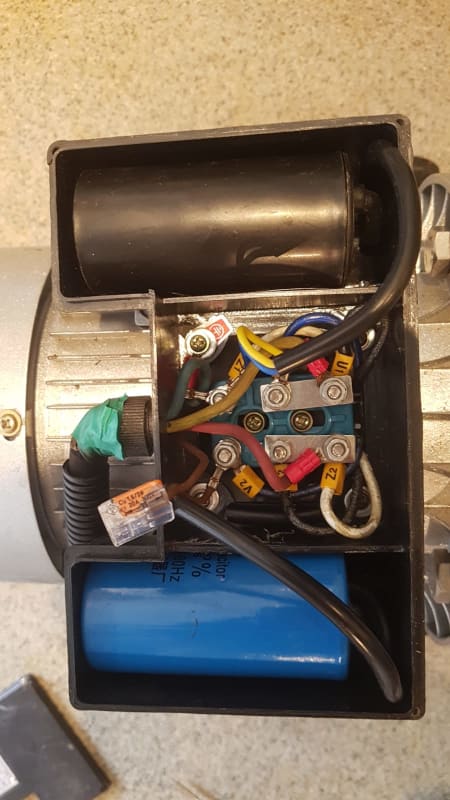
WhatsApp_Image_2022-07-21_at_1.23.15_PM_o9wfmx.jpg
 
Replies continue below

Recommended for you

Not much to work on. More info is needed; VFD specs, motor ratings, pump ratings, etc.
 
Hi, brewersean
If the motor is three-phase , you have to use wiring for single-phase input and three-phase output.
Motor must be three-phase, originally connected in Wye, then reconnected to Delta (you probably skipped that part).
No capacitor is needed.
You can change direction by swapping two lines on motor.
There is another way to reverse motor if you want to use an external switch ( on/off, forward-reverse and external potentiometer).
Regards
More at:
Winding Design and Motor Repair

 
What capacitor?

The VFD can reverse the motor, no wire swapping necessary.
 
Dear Mr. brewersean (Bioengineer)(OP)21 Jul 22 11:27
"....I have a single phase 16A 22OV power supply for #1. a 3 phase motor I am trying to install a VFD on.
I have two problems, #2. the pump direction is backward (regardless of switching any of the WVU wires) and #3. after about 42hz the VFD trips on ''Short Circuit/Current overload/Power Module protection'' #4. I am lacking.... whether the capacitor is necessary or in the way,
. "
#1. Please take a photo of the motor name plate showing the rated Voltage, Frequency, Power (kW), Current (A), IEC/NEMA standard, 6 wires (IEC) or 3/9 wires (NEMA) leads, If IEC 6 wires, there are two possibilities, it is either in Y or D. Check on the motor terminal block. It is now liked in Y or D.
#1.1 Attention: since your 1-phase supply is 220V 1-phase , the VFD 3-phase output can only be 220V 3-phase. Check that the motor is linked for 220V 3-phase.
#2. If the VFD is set to Forward but the motor is running reverse; swap any two wires on the VFD terminal or at the motor terminal block.
#2.1 Note: The VFD has " reverse" possibility. It is strongly recommended to set VFD to say "Forward" and the pump is rotating in the "correct" rotation. If rotating " backward" , swap the 2 wires (see above #2); NOT by changing the VFD setting.
#3. Check that the motor is linked for 220V 3-phase.
#4. No additional capacitor is required.
#4.1 Attention: The 220V 1-phase VFD ( rated Current in A ) shall be sized about 2 times the 220V 3-phase load rated current.
Che Kuan Yau (Singapore)
 
If the motor has a capacitor, it is not likely a 3 phase motor. If that is the case, you would not use that VFD and you would change direction by changing how the capacitor is wired.


" We are all here on earth to help others; what on earth the others are here for I don't know." -- W. H. Auden
 
Thanks for all the replies.

My apologies, I think I got the phasing of the motor wrong. It looks like a single phase motor.

It is still spinning the wrong way. I see on here ( that I can change the linkages to reverse the direction..

However I am confused about two things:
1. Why has installing the VFD changed the direction of the motor? It was running the right way before the install.
2. Is my blue capacitor wired wrong? Based on the link I pasted above it should run between the terminal where V2 is and the terminal where V1 is, correct? (V1 is at the ''top middle'' terminal in the photo)

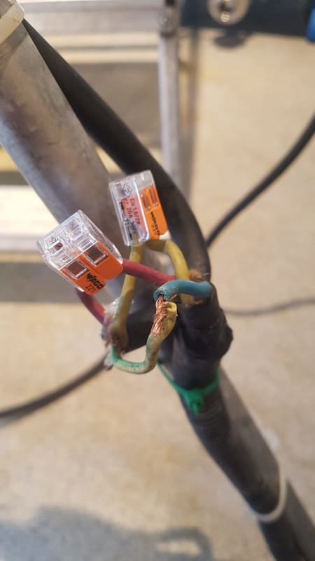
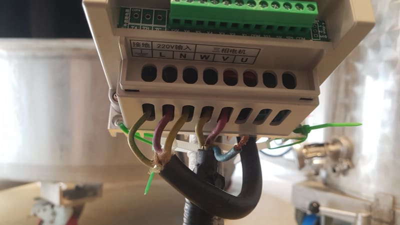
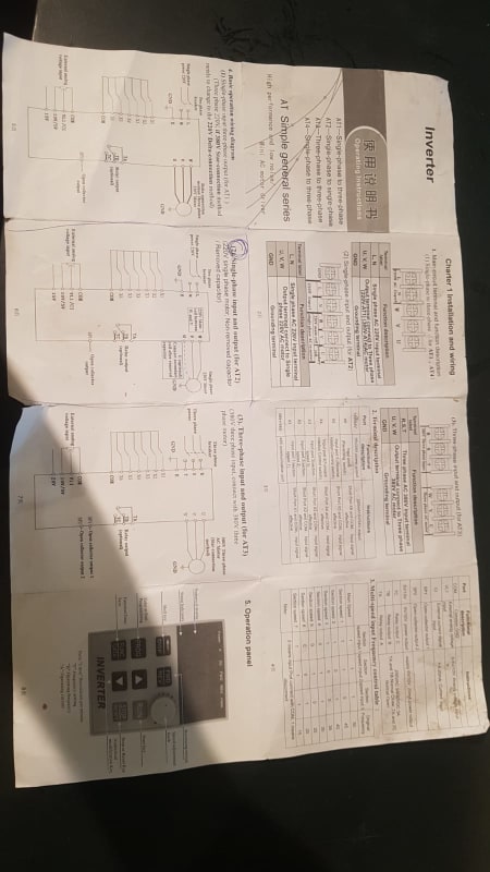
Below are the wiring of the VFD and the wiring before the VFD.

WhatsApp_Image_2022-07-22_at_3.21.13_PM_lhbsze.jpg
WhatsApp_Image_2022-07-22_at_3.33.34_PM_rcen4i.jpg
WhatsApp_Image_2022-07-22_at_3.34.07_PM_gs8nha.jpg
 
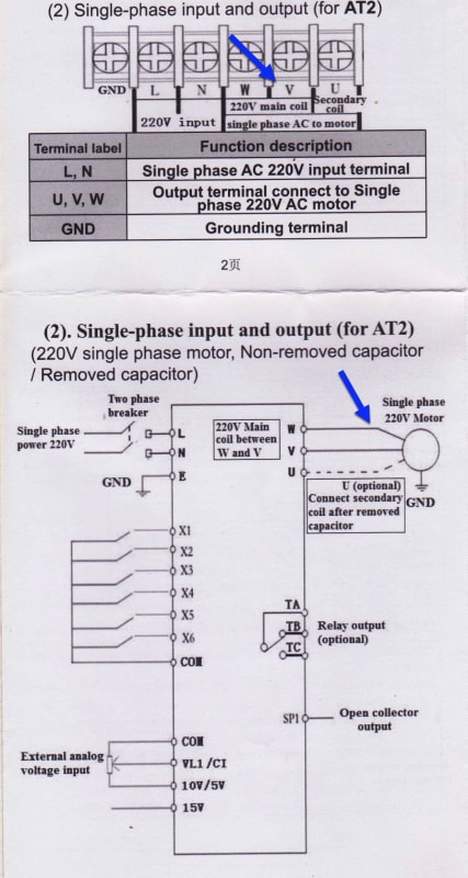
If it is a single phase motor, you should use AT2 wiring.
They say it is possible to connect a single-phase motor with capacitors as well as with removed capacitors.
As usual, the Chinese instructions are incomplete and confusing and do not help at all.
Maybe you should search on Youtube.
Someone must have been through that chaos.
Frankly, I doubt it will work.
I would solve it by converting the motor to three-phase.
 
Thanks for the reply zlatkodo. Firstly, Can you tell me what AT2 wiring is? In any case, I am surprised you say you doubt it'll work. Why not? Regardless of the Chinese instructions, etc, it is certainly possible to wire a VFD to a single phase motor, correct?


Any other suggestions out there?
 
I have done more research and it seems if I slowly ramp up speed on the VFD, it doesn't trip.

As for the rotation direction, it seems reversing the polarity of the starting capacitor should reverse the rotation direction.

MY QUESTION IS: shall I also reverse the polarity of the running capacitor?

Thanks,
Sean
 
AT2 wiring is for single-phase supply and single-phase motor.
U-terminal should be connected also.
For reversing rotation you have to interchange the beginning and end of one phase winding (main OR auxiliary phases, not both of them).
It can be complicated if you don't have enough experience.
It is not entirely clear from the instructions how to connect a single-phase motor. Where to connect common lead of motor: to V or W?
If the motor has a start-capacitor, then it also has some kind of switch to turn it off (centrifugal, electronic or similar).
If the capacitors are to be removed, that switch should also be removed. ETC, etc..
Also, sometimes a single-phase motor is an ordinary three-phase motor connected for single-phase use. I see 6 leads from the motor and it could even be that case.
If so, you're in luck.
Tech Support in Winding Design and Motor Repair

vv_thjgeo.jpg
 
Thanks again for the reply!

I was able to rewire it to get it to spin in the right direction.

You say the U line should be connected? I have it un-connected now, because the directions say ''connect secondary coil after removed capacitor'' but I still have the starting and running capacitors connected.

The only problem now is the tripping on current. I think the reason is because the bearings of the pump aren't that good so the friction increases the starting torque necessary to get it spinning. Not sure if there is anything I can do to increase the starting torque? Is this where the U line comes in??
 
1. Why has installing the VFD changed the direction of the motor? It was running the right way before the install.

A VFD always outputs ABC phase rotation regardless of the incoming phase order. So, a motor running the right way on line power might reverse when connected to a VFD.
 
Thanks for the responses. There aren't any parameters I saw on there that have had an effect on the VFD tripping upon starting up. When I first attached it, it only tripped at about 3OHz. Now it is tripping before it even gets to its minimum frequancy of 2O.

Any other ideas before I give up?

Sean
 
I've just beenthinking..

When I take the VFD out and just wire it straight to the pump, it spins fine. Obviously it's more or less instantaneously 1OO percent RPM immediately.. so I'm wondering, is there a way I can set the VFD to start the pump at full speed, then allow me to lower it? That way I'm sure I can get it moving, rather than the slow ramp up which, I think because my bearings are not great, is causing the current trip.
 
Application request a fast response to full speed? What is maximum allowed time to reach full speed?
What speed range do you need to cover with VFD? Time to reach a new speed (lower or higer than actual speed) is important?!
 
Hi, brewersean ,
Probably that pump has a centrifugal switch which has the task of turning off the start capacitor when the motor reaches a speed close to the rated speed (eg 3000 rpm at 50 Hz in case of 2-pole motor).
Bare in mind that this switch will turn on the start capacitor again when the speed drops below a certain value. This means that by reducing the frequency, you reduce the rpm, the starting capacitor turns on again and this is the reason for the excessive current and trip. But not only that, there is also a danger of explosion of the starting capacitor because it is intended only for short-term operation.
That's why I said it won't work and my recommendation is to convert it to a three-phase motor if power supply via vfd is necessary at all.

Our FB page
 
Status
Not open for further replies.

Part and Inventory Search

Sponsor