Continue to Site

Eng-Tips is the largest engineering community on the Internet

Intelligent Work Forums for Engineering Professionals

  • Congratulations KootK on being selected by the Eng-Tips community for having the most helpful posts in the forums last week. Way to Go!

Simple Statics related Analysis 4

Status
Not open for further replies.

DimzK

Structural
Jun 24, 2018
30
Hi All,
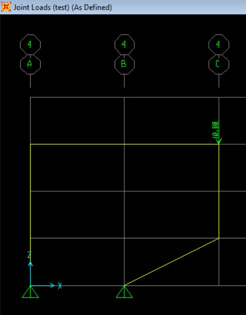
I have a simple frame with the following loads and the support conditions.
Capture1_yqzdqd.jpg


To solve the reactions manually, it is easy to get the vertical reactions by solving for moments equilibrium at the supports (to equal zero).
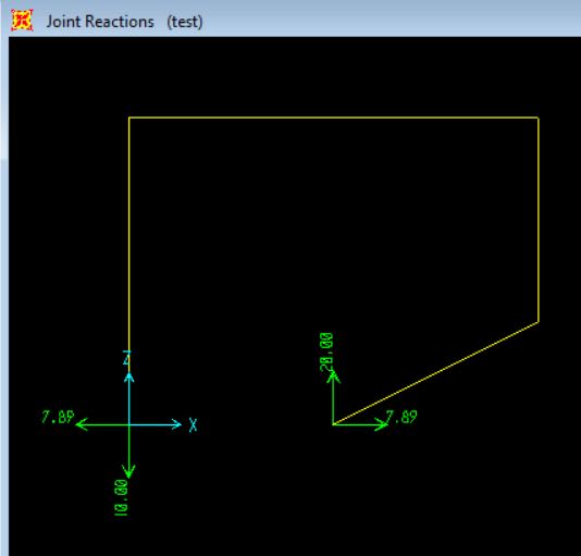
What I don;t get is how to solve for the horizontal reactions of 7.89kN at the supports. Am I missing something obvious here or is this not as simple as it looks?

The SAP results are below:
Capture2_xnmgiq.jpg


If there is a simple manual hand calculation to find this, could you please show me.
Thanks,
Dimuth
 
Replies continue below

Recommended for you

As your structure is statically indeterminate there is no "simple" way to solve this.
 
correct...you need more than 3 equilibrium equations ......
 
To solve by "hand":
Use statics to solve for vertical reactions.
Assume horizontal reactions.
Using statics, you can then find internal forces and moments in each beam section.
Using beam tables, you can find corresponding deflections and rotation angles.
Work your way around the loop totaling up deflections at each node.
Adjust the "assumed" horizontal component to make the final deflection come out to zero.
This would lend itself to a spreadsheet for solution.
Really simple with structural software.
Slow and tedious to actually do by hand. Although, it should be linear, so finding deflection for two different values of horizontal load would give you the solution.
To match the computer solution, you might need to consider shear deflection and axial deflection.
 
Moment distribution. An Engineer's crossword puzzle.
 
this is because you've modeled two rigid constraints.

maybe a limitation of your software. If solved by hand you'd put one reaction on a roller and have no X-reactions. If you want "truth" then put a spring between your structure and the ground (this'd represent the finite stiffness of the attachments, rather than the infinite stiffness of your constraint.

IMO, someone using FEA should understand these limitations in the results.


another day in paradise, or is paradise one day closer ?
 
All, Thanks for the answers, it is clearer now.
 
Obviously, I don't know all of the ins and outs of what you're up to here but, for many a practical structure, I'd consider the model below to be eminently suitable. It has the advantages of being a) statically determinate for computational expediency and b) robust in terms of having a simple load path to which any ancillary joint fixity at the top right could be considered a "bonus". Oftentimes, the simplification that makes your calculations easy and the simplification that makes your structure reliable are one and the same. Like I said though, I really have no idea what your real world structure is so do take my suggestion with a grain of salt. For all I know, perhaps this may be just a software verification exercise etc.

c01_rqpyk4.jpg
 
Like others have typed, it's indeterminate, so it can't be solved with only statics.

You might try the Force Method, aka the method of consistent deformations. The frame has only one redundant reaction, so the solution would take about a page of work.
 
How does KootK's structure work ? Actually, very cleverly … making the frame into two two-force members and statically determinate.

another day in paradise, or is paradise one day closer ?
 
Thanks all, this is just a hypothetical structure. I am not building this in real life. Just reading the Canadian building code, there was some mention about being extra careful with inclined members that carry gravity loads that may impose lateral loads at supports. I am just going back to the basics trying to get some idea how these type of frames may work for my own research .
 
As a decent first order approximation, you can assume a pin midspan of the horizontal beam near the the point of inflection and solve it statically:

portal_frame_onvwbp.png


Look up "portal frame method" of analysis.
 
Shipping at the inflexion points is a clever way to simplify.
 
Change one of the supports to a roller.
Calculate the horizontal deflection of the roller under the applied loading (say Δ).
Apply a unit horizontal force at the roller and calculate deflection (say δ).
Horizontal force H = Δ/δ.

BA
 
Ok it is clear that with two pin connections, it is statically indeterminate and as such, it is hard to solve by hand.
So I can see as many suggest if one of the supports are rollers, then there is not going to be any horizontal reaction.

But suppose in a real life situation, this is a welded steel frame (With rigid connections at each node) and say two pin supports where the steel frame is connected to pad footings with a bolted end plate (not a moment connection), in real life, is there going to be a horizontal force on those pad footings? As the software is showing?

I think there has to be, obviously the software must use force method or method of displacement to solve for the reactions. So if there is a horizontal force in to balance out the matrices, then yes it is there in real life too.
 
DimZ said:
Ok it is clear that with two pin connections, it is statically indeterminate and as such, it is hard to solve by hand.

no it is not hard to solve...it is basic knowledge for structural and mechanical engineers.... [dazed]

 
dimz said:
is there going to be a horizontal force on those pad footings?

Yes, there will be. Even in a moment frame with vertical columns under gravity load you will have shears at the base. I had a project where a long-span (~260 ft) moment frame sheared through the anchor bolts in the footing. The base connection had not been completed and the frame would have collapsed if the purlins to the next frame had not restrained the top of the frame from falling out-of-plane.
 
"is there going to be a horizontal force on those pad footings?" … yes, if you don't have a roller on one support (and then you'd nned to keep the fixed frame at the load point).


another day in paradise, or is paradise one day closer ?
 
Status
Not open for further replies.

Part and Inventory Search

Sponsor