Continue to Site

Eng-Tips is the largest engineering community on the Internet

Intelligent Work Forums for Engineering Professionals

  • Congratulations KootK on being selected by the Eng-Tips community for having the most helpful posts in the forums last week. Way to Go!

Simple Strength of Material question 10

Status
Not open for further replies.

BFstr

Structural
Jul 20, 2009
54
Hi
We are in debate in office on the correct answer to this problem:

A uniform straight rod AB (A if fixed, B is free end)with total length of 3 meter is under some axial loads that causes strain of Ɛx = 0.01x^2
What is the axial displacement of the end B in terms of centimeter?

Interesting question. Looks simple !!!
Appreciate all steps reaching your answer

Thanks

 
Replies continue below

Recommended for you

So our coefficient units are (1 / cm) where cm = centimeters? In the OP, is Ɛx written as Esubx, or E times x?
 
"is Ɛx written as Esubx, or E times x?" ... I wondered about that too ... so I stated "strain(x)", hoping the OP would either agree or say "no, I didn't mean that; I meant ..."

"Hoffen wir mal, dass alles gut geht !"
General Paulus, Nov 1942, outside Stalingrad after the launch of Operation Uranus.
 
Gentlemen
The strain function is epsilon sub x.
It is Not epsilon times X.
Epsilon sub X denotes the strain function along X axis which is the longitudinal axis of the bar.
 
The 0.01 coefficient in the OP has implied units of 1/L^2. It is reasonable to assume that it is based on x being in metres, because the strain would be rather large if it was in cm.

As noted by Denial, a uniformly rotating bar would have that strain distribution, with zero strain at the free end. The deflection relative to the free end would therefore be as noted by HTURKAK; 0.09 m. or 9 cm.

Doug Jenkins
Interactive Design Services
 
BFstr said:
A uniform straight rod AB (A if fixed, B is free end)with total length of 3 meter is under some axial loads that causes strain of Ɛx = 0.01x^2

Since the length of rod is given in meters, the expression for strain assumes x is in meters. So there are axial forces applied to the rod which cause strain of 0, 0.01, 0.04 and 0.09 at x = 0, 1, 2, and 3m respectively. HTURKAK nailed it when he found the total strain to be 0.09m, 9cm or 90mm.
 
IDS.[ ] The rotating bar I was hypothesizing does not have exactly the strain versus location relationship described by the OP (Ɛ[sub]x[/sub]=ax[sup]2[/sup]).[ ] It will have the form Ɛ[sub]x[/sub]=ax[sup]2[/sup]+bx, where b is not zero.

[sub][ ]—————————————————————————————————[/sub]
[sup]Engineering mathematician / analyst.[ ] See my profile for more details.
[/sup]

 
Denial said:
The rotating bar I was hypothesizing does not have exactly the strain versus location relationship described by the OP (Ɛx=ax2). It will have the form Ɛx=ax2+bx, where b is not zero.

Surely the stress and strain at the free-end are zero?


Doug Jenkins
Interactive Design Services
 
Definitely.[ ] But their first derivatives wrt x are not zero in my bar, whereas they are zero in the OP's postulated problem.

[sub][ ]—————————————————————————————————[/sub]
[sup]Engineering mathematician / analyst.[ ] See my profile for more details.
[/sup]

 
c'mon OP, please show the derivation of the strain function.

Or is this a thought exercise ? In which case, to make sense of your function, "0.1" have the units of L^-2, in order that strain is dimensionless; then the integral is 0.01*x^3/3 (as per HTURKAK), dimension meters, and value is 0.1*27/3 = 0.09m. Though, of course, the units of "0.1" don't need to be m^-2, they could be mm^-2, or km^-2, or ...

"Hoffen wir mal, dass alles gut geht !"
General Paulus, Nov 1942, outside Stalingrad after the launch of Operation Uranus.
 
Denial said:
Definitely. But their first derivatives wrt x are not zero in my bar, whereas they are zero in the OP's postulated problem.

OK, I see your point.

But the strain distribution doesn't seem that mysterious. A linearly increasing distributed axial force, increasing from zero at the free end, will give the strain distribution in the OP, and the total deflection of 0.09 m, as originally found by HTURKAK.

Doug Jenkins
Interactive Design Services
 
BFstr said:

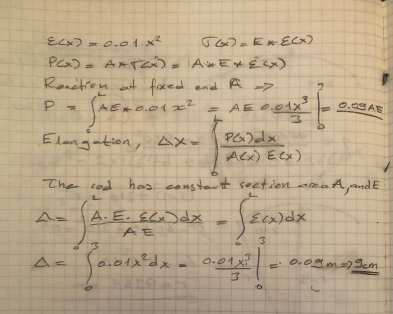
I just see you respond ( my time zone UTC+7 )and i prefer to respond when my nick name is explicitly stated. It is hard to respond with using limited symbols available at forum . So i performed the below small hand calculation then take the photo . If the strain is a function of length , the force applied will also be a function of length (x) and in this case the applied load is parabolic distributed along the length .

Stub_elangation_dye6sx.jpg


I did not mess the units. In this case the strain Ɛx = 0.01x^2 is a function of length and the dimension L**2 .


EDIT; Similar real case , when the calculation of elongation of tension pile or shortening of compression friction pile is necessary . The resisting frictional force developing at periphery of pile is a function of length ,X .


Use it up, wear it out;
Make it do, or do without.

NEW ENGLAND MAXIM
 
HTURKAK,
Thank you so very much. Very well done and explained. Greatly appreciate it for the photo of hand calculation. Your method is justifying and yes you did not mess with units. Greatly appreciate it.

Sincerely
BFStru
 
@HTURKAK, yeah, sorry ... and others solved that by giving the constant some dimensions.

@BF ... sorry, but you needed to see the integration of a simple function ? HS math ?? and for the last time (I promise) please show the derivation of your strain function.


"Hoffen wir mal, dass alles gut geht !"
General Paulus, Nov 1942, outside Stalingrad after the launch of Operation Uranus.
 
rb1957 said:
@BF ... sorry, but you needed to see the integration of a simple function ? HS math ?? and for the last time (I promise) please show the derivation of your strain function.

Well FFstr has already posted:
Assume due to an unknow loading (however axial for sure)has caused this strain equation governs for the bar. How can you get the displacement of point B in this rod having this strain equation?

and I have pointed out that a linearly increasing distributed axial load, with zero load at the free end, will give that strain distribution, so what more do you need?

Doug Jenkins
Interactive Design Services
 
Thank you so very much for your support and statement IDS.
 
so this is just a thought exercise ? As noted above, this is a very unusual thought !

"Hoffen wir mal, dass alles gut geht !"
General Paulus, Nov 1942, outside Stalingrad after the launch of Operation Uranus.
 
Note that this rather unfocused and ill posed question has NOTHING to do with “strength of materials” but is rather just involved with a strain distribution for an undefined theoretical situation solved by simple integration.
 
This question has not been posted on Aerospace people forum. And no need to be rude and insulting if you think the question is way below your expertise. No one has forced you to respond. Be professional rather than rude.
People are communicating with different level of knowledge and experience and not nice to be rude and insulting. Especially when you come from different discipline. I appreciate not hearing any more from Aerospace experts which I didn't ask them to reply to a Structural engineer.
 
sorry, SWC is IMHO correct, and also not being rude nor insulting. The initial responses where "how can this be ?". The solution was, being blunt, trivial; and did require some interpretation of the equation (oh, that constant must have units ... we can identify the dimensions but the units (m, cm, km ?) are undefined and left to assumption.

Maybe this should've been posted on the "student" forum (since the solution was so basic). You've posted on one of the professional forums where we expect professionals are asking questions of a professional nature and can understand and work with professional degree of knowledge.

"Hoffen wir mal, dass alles gut geht !"
General Paulus, Nov 1942, outside Stalingrad after the launch of Operation Uranus.
 
+1 to rb and SWC above. At the start of this thread we asked for a bit of context to the question, and was simply responded with "assume a magical handwaving power has created this scenario". Because this forum is generally intended to assist with profession design and detailing, a theoretical situation with a straightforward solution is not generally the first expectation here, so the request for context that would help us to better define and understand the problem. Sounds like this was a homework question more so than an actual design or detailing situation.

The initial question was unclear and unfocused, I agree that it was better suited for the "student engineering" forum.
 
Status
Not open for further replies.

Part and Inventory Search

Sponsor