Continue to Site

Eng-Tips is the largest engineering community on the Internet

Intelligent Work Forums for Engineering Professionals

  • Congratulations The Obturator on being selected by the Eng-Tips community for having the most helpful posts in the forums last week. Way to Go!

Simple Three Sided Box - Trying to Understand Deformed Shape 6

Status
Not open for further replies.

sticksandtriangles

Structural
Apr 7, 2015
486
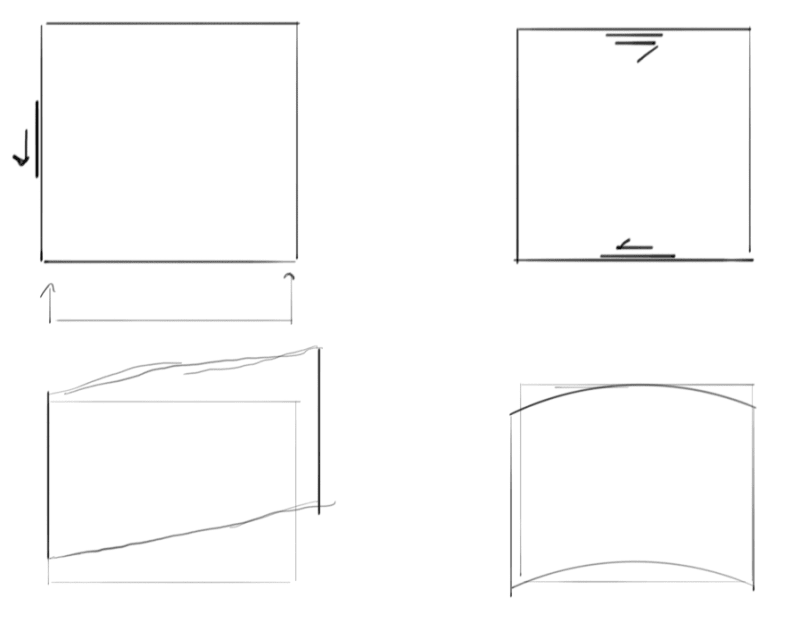
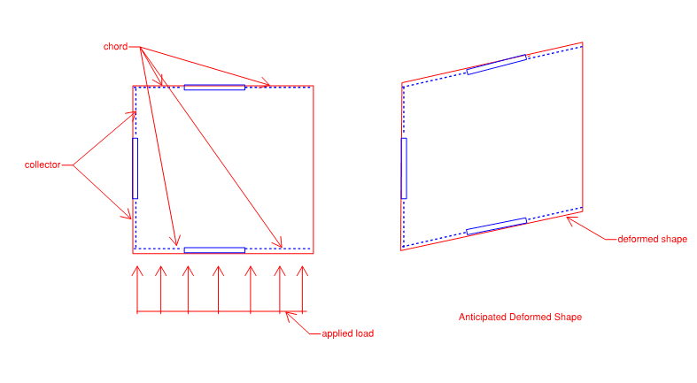
So, I was trying to build a simple model of a three sided box in Etabs (with a membrane element, no rigid diaphragm assumption) and was expecting get a deformed shape like the following, (expected mostly shear deformation of the membrane element):
Deformed_shape_safwqu.png


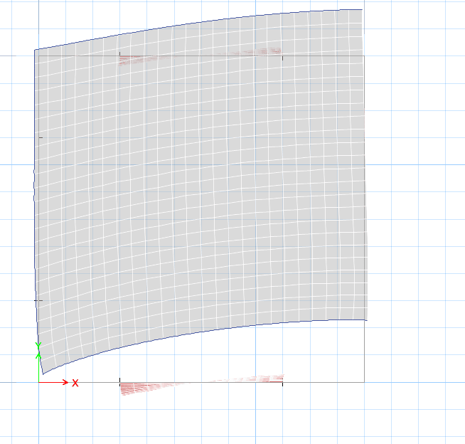
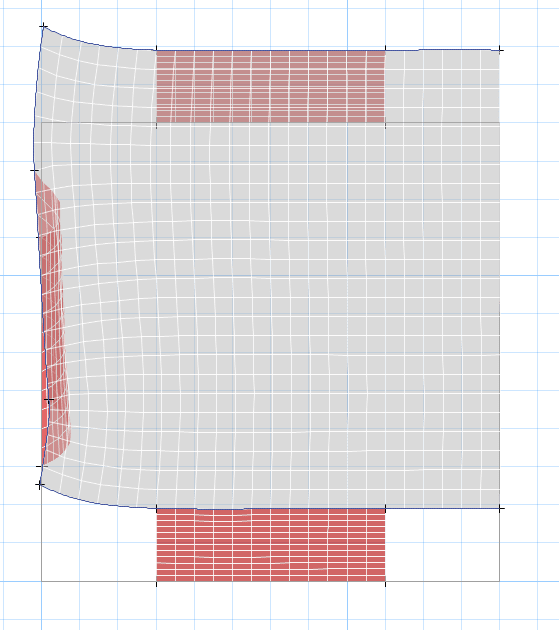
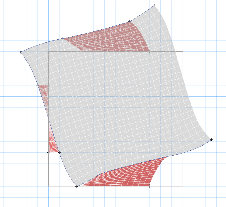
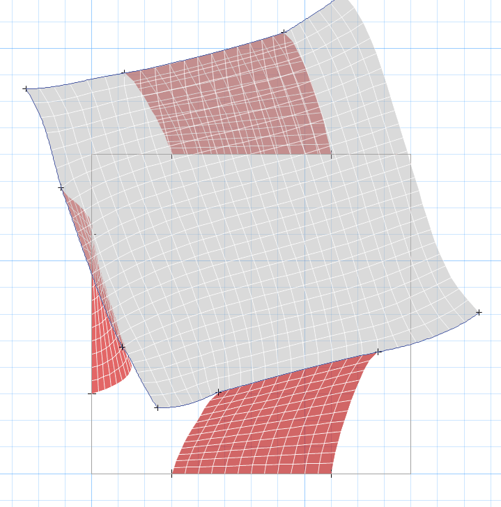
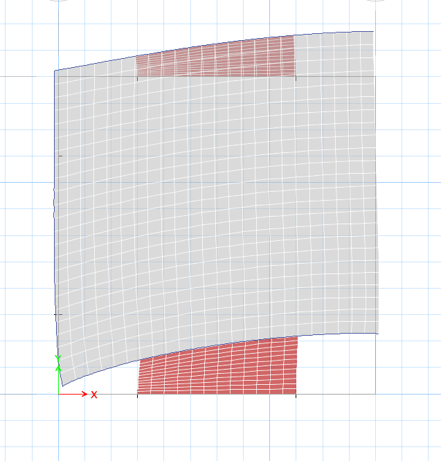
When I run my analysis, I get the following deformed shape:
etabs_deformed_wx0x6l.png


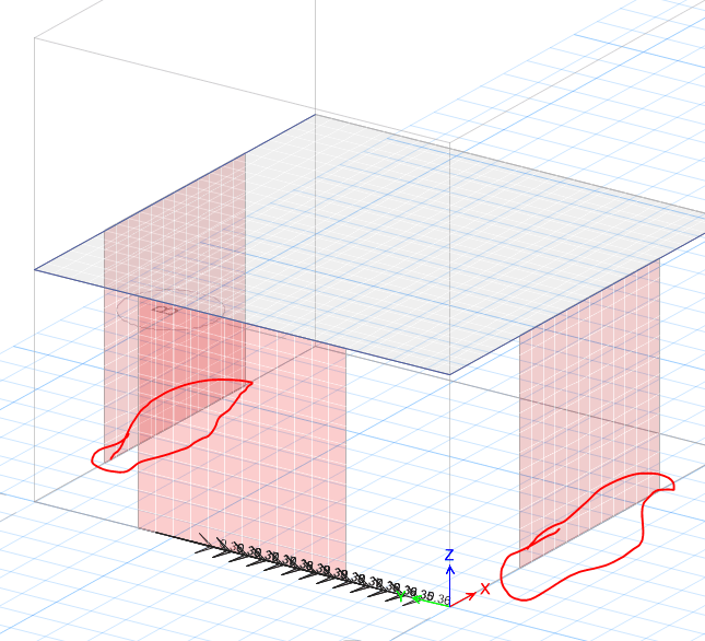
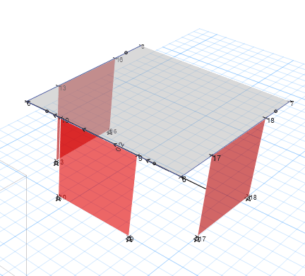
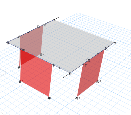
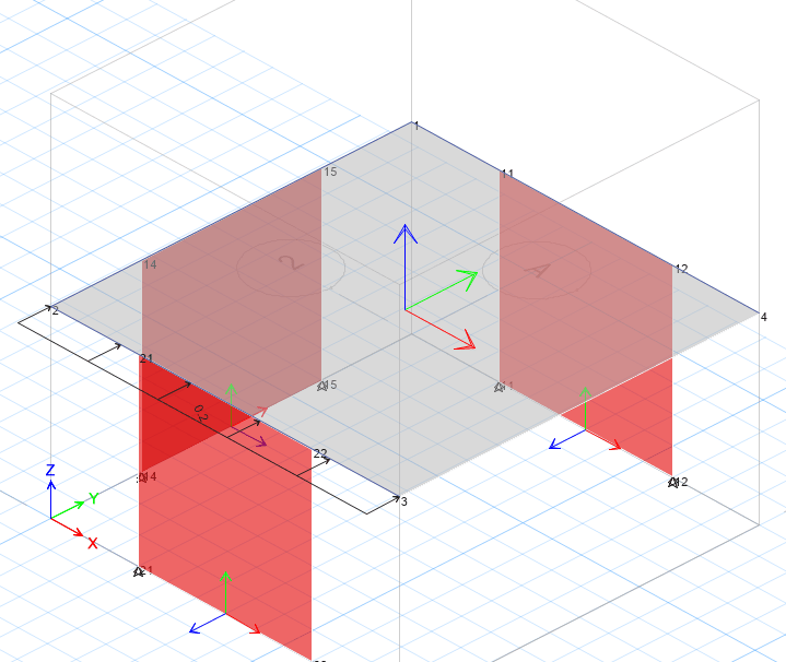
Applied loading looks like the following:
applied_qhe5xf.png


A few notes:
- I am unsure why the free (right) edge of the diaphragm does not deflect in a smily face upward manner​
- Floor is modeled as a membrane element​
- Chords and Collectors are modeled as steel beams​
- Self weight is turned off, only load applied is the lateral load shown above​

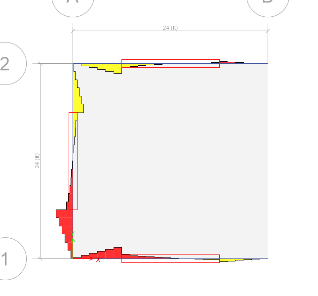
The other interesting thing is that the axial load in the chords and collectors exactly matches what I would expect (red = compression, yellow = tension):
chord_and_collector_force_byoot4.png


Questions:
- Do you agree with my anticipated deformed shape?​
- Any ideas on why Etabs shows the deformed shape that it does? Maybe something in our hand methods for diaphragms that does not match what Etabs is doing?​

Seems like the shear stresses in my diaphragm build up as you move page left (like you would typically calculate)
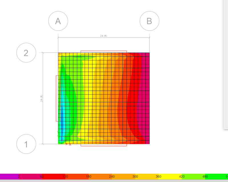
shear_stress_uasjc2.png

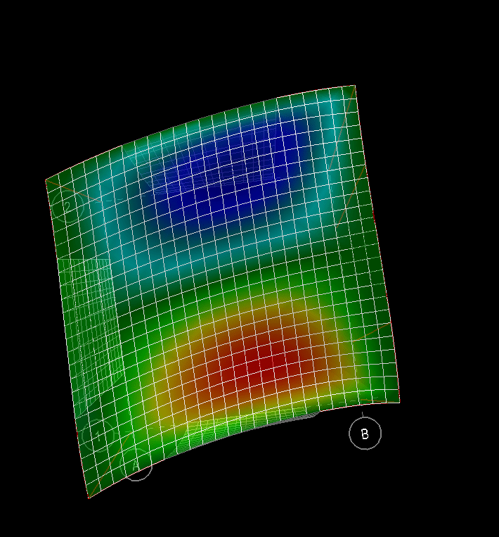
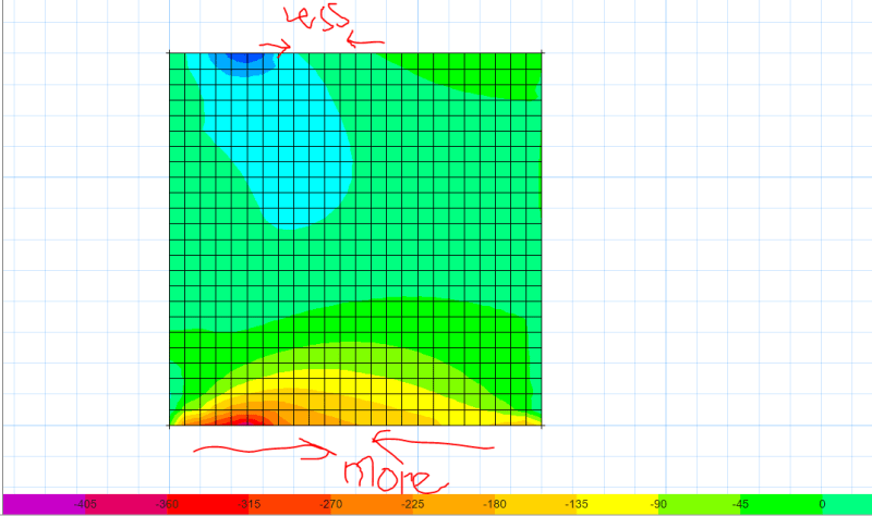
Only thing that maybe wrong with traditional assumptions is there seems to be some non-neglible axial stresses in my membrane element (see image showing compressive stress build up on front edge of diaphragm).
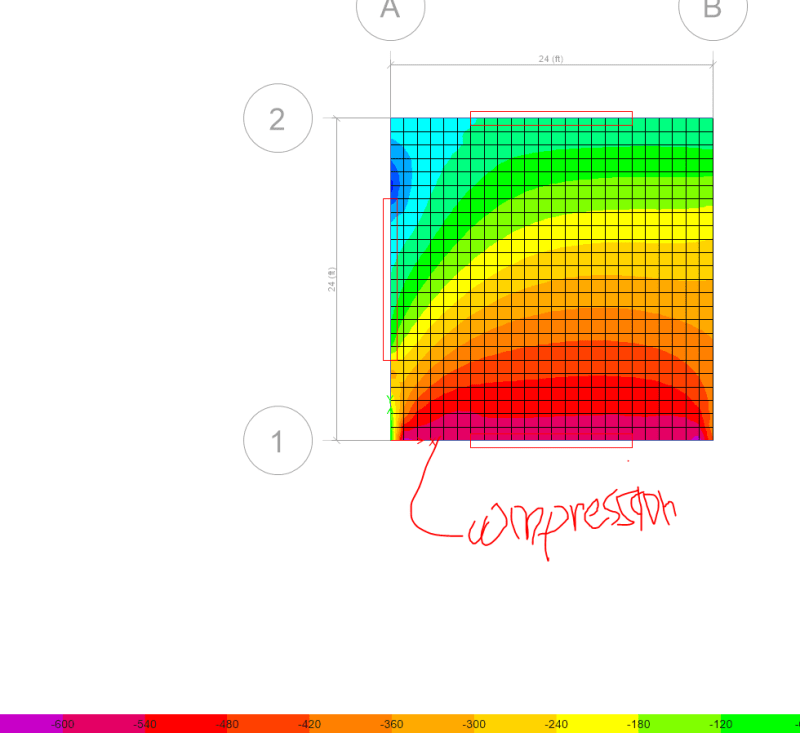
axial_stress_gz76h3.png

I've played with bringing down the axial stiffness but it makes my deformed shape look very odd.

Thoughts appreciated!


S&T
 
Replies continue below

Recommended for you

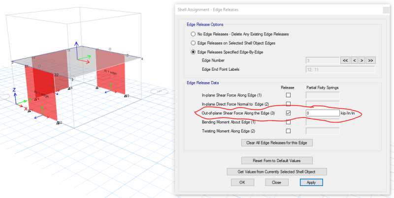
So, my mind went to the weak axis stiffness idea as well and tried the following ...
shell_releases_hztd4b.png


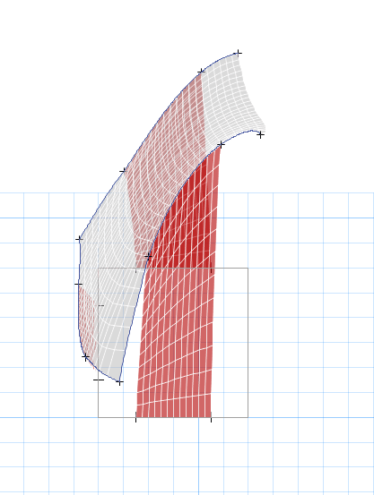
Releasing the shear in the out of plane direction at the top yields much the same deformed shape:
Deformed_shape_pqjumf.png

You can also see no reactions in the out of plane direction at the base of the wall:
y_rxns_fa9vnb.png


I am having a hard time understanding why semi rigid action would create "reverse" curvature in my chords though. Mind explaining?

S&T
 
Just thinking out loud... deformed shape sort of looks like a pinned base moment frame if you turned it 90 degrees:
pinned_base_moment_frame_fpn9wc.png


Still not sure if my intuition is correct on the deformed shape.

S&T
 
If deflections make no sense and are not realistic, something is wrong with the model.

Mike McCann, PE, SE (WA)


Thanks for the thoughts msqaured48, like I had mentioned; do you agree with my assumed deformed shape in the original post?

My goal here is to try to understand why the model is behaving the way it is and potentially get it to mimic/match our assumed diaphragm deformed shape.


S&T
 
Your assumed deformed shape assumes a perfectly flexible diaphragm (or pretty close to one). But, that's not possible for this case. The shear gets resolved back to the one main wall, but what about the moment caused by that shear. That becomes a shear in the other two walls.... Which is only possible if you get semi-rigid / semi-flexible diaphragm behavior.

Try using super position. Apply a shear load at the main shear wall, see what it's deflected shape looks like (probably closer to what you originally assumed). Then apply equal and opposite shears to the other walls and see what that deflection looks like. Add the two loads together and then see what this combined deflection is. It should be pretty close to your original eccentric shear load.
 
Josh, thanks for your input.

Everything you mentioned in the first paragraph makes perfect sense... I guess my main question is the odd deformed shape of the diaphragm (cannot understand deflected shape at all).

I explored your super position idea:

Shear Load:
shear_load_jwrosw.png

Shear Deflection:
shear_deflection_cktj5o.png

Torsional Load:
torsional_load_kc1bap.png

Torsional Deflection:
torsional_deflection_xoqkt9.png


Combined Deflection (shear and torsional case):
combined_deflection_iaauk4.png


Again for reference (the original deflected shape with eccentrically applied load).
combined_deflection_eccentric_load_last_mvgmgk.png


The combined superposition method you mentioned produces results more in line with what I would have anticipated (see smile face up at free edge).
The eccentric load method I orginally presented also results in more deflection which I would expect (both images have the same scale factor for deflected shape).

Still at a loss... might try this in another program and see if I get similar results to either of these models.


S&T
 
What are the end releases of your steel beam collectors where they meet at the diaphragm corners? Long shot, but could they be stiffening those corners?
 
Jayrod,

steel beam collectors are pinned ended members.

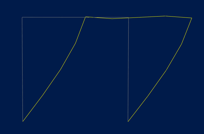
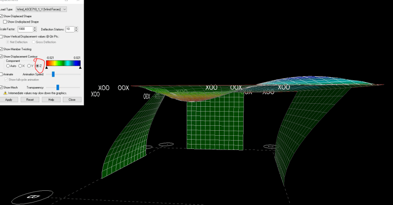
Celt, that graph is for vertical deflection, you can see the deflected shape of the diaphragm almost looks like a moment frame beam. Note that I have turned off out of plane stiffness in both models so I assume the deflection I am seeing is just compatibility deflection.
image_lbrckl.png


You bring up a good idea though, maybe axial stresses in the membrane element?
The image below is the axial stress from the etabs model (I do not think this is available to me in RAM SS).
membrane_stress_auxxgd.png


This would explain the deformed shape I guess... not sure if it is reality though?


S&T
 
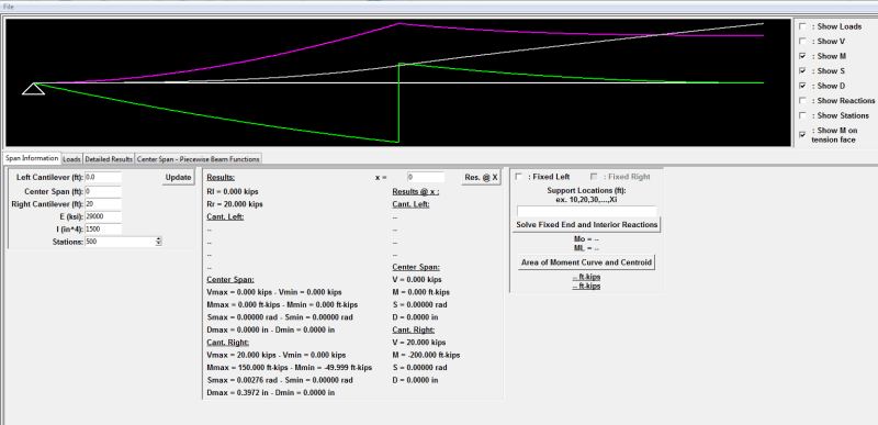
Trying to show it another way as a simple cantilevered beam,will be slightly off since the left can't deflect.

So I have added a moment at about mid cantilever to produce a 0 moment reaction at the fixed end, so left support only has a vertical reaction and the moment represents the couple formed by the walls.
Green line is the moment diagram
Purple line is the cross section slope, in the larger model that point moment becomes spread out so the peak would be more gradual
Grey line is the centerline deflection

Capture_yeeizk.png


Same thing with a series of point moments to smooth out the slope:
Capture_qlwcdh.png


Open Source Structural Applications:
 
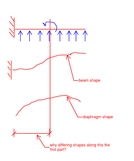
That's a good analogy celt83, the part that throws me off though is that my model starts in the opposite direction of your assumed beam shape:
deflected_shapes_x6vmrs.png


Makes perfect sense that the end would curve back now.

These counter intuitive (at least for me) things are always a little fascinating to explore.

S&T
 
so in my model it's a fixed-free simplification with a forced 0 end moment. This simplification also ends up creating boundary conditions of 0 slope and 0 deflection at the support. In reality your wall only provides a vertical support but both slope and deflection can and likely will be non-zero which would get you to the actual diaphragm deflected shape.

Open Source Structural Applications:
 
Honestly, I think the pure shear deflected shape goes a decent way towards explaining the deflections you were seeing. At least some of the weirdness in curvature close to the main shear resisting wall.

If you're still not comfortable, try making the semi-rigid diaphragm extremely rigid. Does that deflected shape of the rigid diaphragm make sense to you. If not, then there is something really weird going on.

If the rigid example makes sense, then try softening it a bit until you start to see the diaphragm deform a little. Does that extra diaphragm deformation make some sense? If you soften the diaphragm more and more, then it should lead to a deflection like you originally saw.
 
I have been thinking about this, and I believe the deflected shape is exactly what we should expect.

A three sided diaphragm is not a cantilever, but rather a simple span beam cut in half. So the deflected shape looks like the deflected shape of half of a simple span beam.

DaveAtkins
 
I'm glad it has not just been me thinking about this : ).

Thought a lot about it over weekend haha... things like this just eat at me. I am still not settled on my understanding of the deformed shape, may just need to accept it as the way it is.

Counter to your line of thinking (just throwing it out there, not sure how valid):

Simple span beam cut in half has a moment released if you make the cut at mid span... our diaphragm cannot have any "moment" per say​

S&T
 
sticksandtriangles said:
Simple span beam cut in half has a moment released if you make the cut at mid span... our diaphragm cannot have any "moment" per say

True, but the "moment" is contained in the two perpendicular shear walls, so I still think this acts like half of a simple span beam.

DaveAtkins
 
I'm definitely on board with the one half simple span beam analogy. I've been mulling this one since it started.
 
Status
Not open for further replies.

Part and Inventory Search

Sponsor