Continue to Site

Eng-Tips is the largest engineering community on the Internet

Intelligent Work Forums for Engineering Professionals

  • Congratulations The Obturator on being selected by the Eng-Tips community for having the most helpful posts in the forums last week. Way to Go!

Simple Three Sided Box - Trying to Understand Deformed Shape 6

Status
Not open for further replies.

sticksandtriangles

Structural
Apr 7, 2015
486
So, I was trying to build a simple model of a three sided box in Etabs (with a membrane element, no rigid diaphragm assumption) and was expecting get a deformed shape like the following, (expected mostly shear deformation of the membrane element):
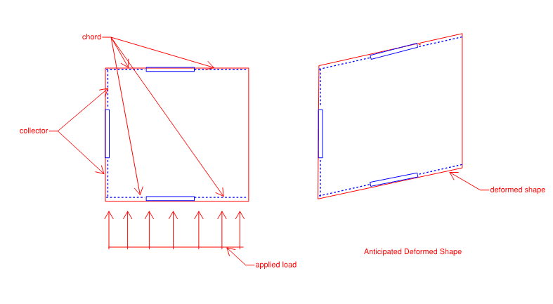
Deformed_shape_safwqu.png


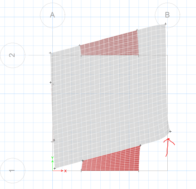
When I run my analysis, I get the following deformed shape:
etabs_deformed_wx0x6l.png


Applied loading looks like the following:
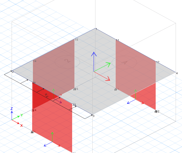
applied_qhe5xf.png


A few notes:
- I am unsure why the free (right) edge of the diaphragm does not deflect in a smily face upward manner​
- Floor is modeled as a membrane element​
- Chords and Collectors are modeled as steel beams​
- Self weight is turned off, only load applied is the lateral load shown above​

The other interesting thing is that the axial load in the chords and collectors exactly matches what I would expect (red = compression, yellow = tension):
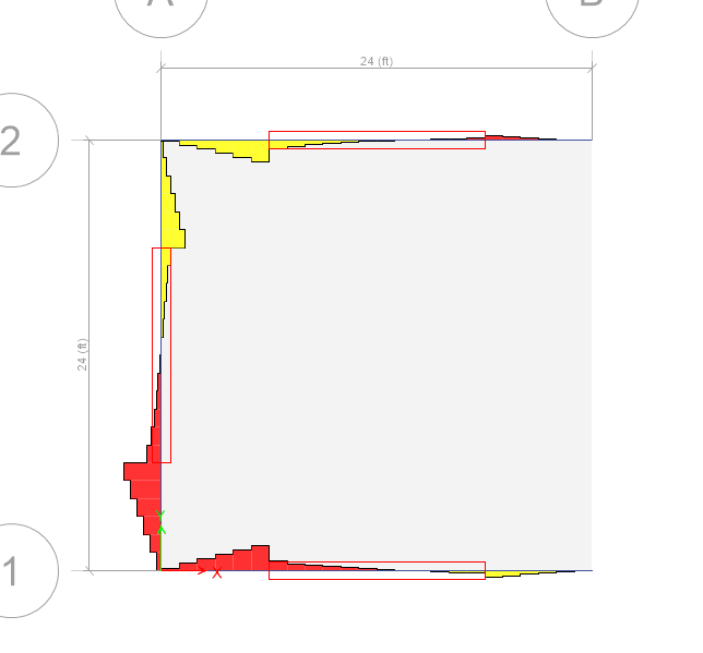
chord_and_collector_force_byoot4.png


Questions:
- Do you agree with my anticipated deformed shape?​
- Any ideas on why Etabs shows the deformed shape that it does? Maybe something in our hand methods for diaphragms that does not match what Etabs is doing?​

Seems like the shear stresses in my diaphragm build up as you move page left (like you would typically calculate)
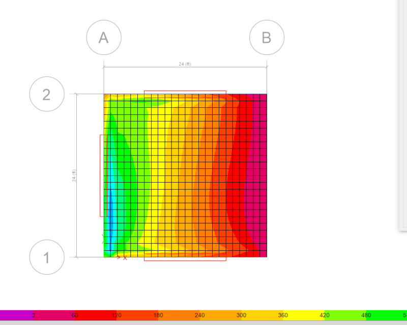
shear_stress_uasjc2.png

Only thing that maybe wrong with traditional assumptions is there seems to be some non-neglible axial stresses in my membrane element (see image showing compressive stress build up on front edge of diaphragm).
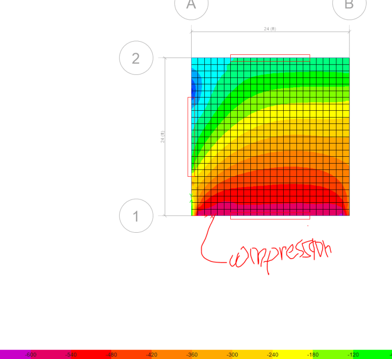
axial_stress_gz76h3.png

I've played with bringing down the axial stiffness but it makes my deformed shape look very odd.

Thoughts appreciated!


S&T
 
Replies continue below

Recommended for you

Agree with DaveAtkins half simple span analogy. Simple shear reaction at the Y shear wall, 0 shear at the "cut" end from sum of Y forces , and the couple formed by the X shear walls gives you the equilibrium moment.

Open Source Structural Applications:
 
So small poll, would anyone have guessed that deformed shape in the original setup? (I would not have as you saw my guess and the curvature was opposite of what I expected. Finally starting to come to grips with this...)

Also, let me know if you think the deflected shape changes if I move the left-right shearwalls all to one side.

I have the images, but don't want to taint the guesses [smile]

S&T
 
The sound of oneself patting one own self on the back should be very, very quiet! But, yes, that deflected shape is what I expected from your initial description of the problem. (That is, you kept changing the "model" until the "model" matched what I expected from the 4-body problem with the wind from the bottom of the picture.)

I am making an assumption this is an outdoor structure subject to wind loads. If not, if the loads on the "roof" are interior from a static mechanical load, the following doesn't apply.

Now: change the wind direction so it from the left side of the picture (into the sheer wall.) You should see two "new" shear walls, one bending wall flexing towards the right. The "roof" will twist more uniformly, but will have an oscillating (flapping) action as turbulence pushes up and pushes down irregularly (in the real world)This flappingf will be exaggerated by the curve of the roof in static flexing: So the curve amplifies the wind force up as it hits the static "flex" you see now, then down as the cantilever roof edge bends and sheds that vortex.

When the wind force is from the right, the whole 3-wall shape traps the wind and amplifies the right-side horizontal force (and all "static" motions you now see in the FEA model.) The deflections of all three walls to the left will be greater. The corners deflection of the roof will be greater.
When the flapping starts again, the corners of the roof will move more than in the "wind from left side" case.
 
JoshPlum said:
Honestly, I think the pure shear deflected shape goes a decent way towards explaining the deflections you were seeing.

That.

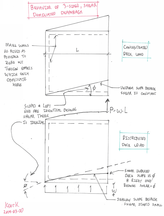
c001_yqwkxt.png
 
We can all be thankful KootK is willing to give up a Saturday to draw free body diagrams of diaphragms[wink]

Seriously, though, that is a nice explanation of what is happening.

DaveAtkins
 
I gave him a star! Definitely helped my understanding [bigsmile].

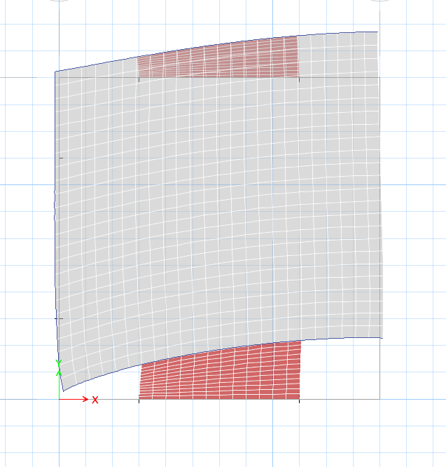
Deformed shape exactly match his assumption with the assigned point load at the end
Capture_i2aepa.png


Again truly appreciative of all that I have learned on this site.

I should free up tonight, I will be able to post the results of shifting the shearwalls all the way to one side, more counter intuitive stuff for me at least.


S&T
 
Status
Not open for further replies.

Part and Inventory Search

Sponsor