Continue to Site

Eng-Tips is the largest engineering community on the Internet

Intelligent Work Forums for Engineering Professionals

  • Congratulations waross on being selected by the Eng-Tips community for having the most helpful posts in the forums last week. Way to Go!

Simplification of 3D Solids to 2D Shells for Pressure Vessel

Status
Not open for further replies.

m_ridzon

Mechanical
Sep 18, 2020
80
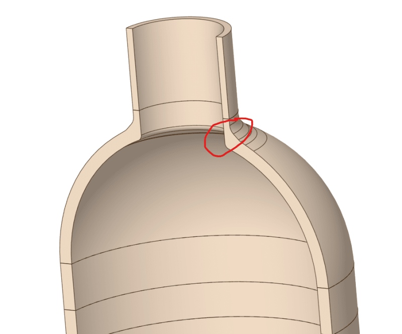
In ANSYS, I have been asked to take a 3D pressure vessel model and midsurface it to a shell model for FEA. See the section view in the image below. My red outline shows a change in thickness. Does anyone know of a clever way to handle this when simplifying to shells?

(before anyone asks, no an axisymmetric model is not suitable for this situation)
3D_to_2D_by9wvm.png
 
Replies continue below

Recommended for you

See Figure 5-A.9 in Annex 5-A of ASME Section VIII, Division 2. I believe that ASME PTB-1 has some good references for this...
 
Just make the shell thickness tapered in the tapered part? Keep the neutral plane constant and adjust thickness equally on top/bottom surface of the shell. Sufficiently accurate for practical calculation and you avoid complications related to eccentric neutral planes (bending and normal force not decoupled etc.).
 
What failure modes and what loads are you assessing? Why would axisymmetric not be suitable here? This is a fairly simple model, why not just use solid elements?
 
cbPVme said:
What failure modes and what loads are you assessing? Why would axisymmetric not be suitable here? This is a fairly simple model, why not just use solid elements?
Creep Fatigue per ASME Sec. 3, Div. 5 is being performed. My colleagues are more adept at that process than me. But they have made it clear that we are not doing an axisymmetric model. I'm fairly sure it has to do with the fact that other components that I did not show in my screenshot will render the situation non-axisymmetric.
 
Status
Not open for further replies.

Part and Inventory Search

Sponsor