Continue to Site

Eng-Tips is the largest engineering community on the Internet

Intelligent Work Forums for Engineering Professionals

  • Congratulations pierreick on being selected by the Eng-Tips community for having the most helpful posts in the forums last week. Way to Go!

Simplifying Clamped Connection

Status
Not open for further replies.

Darryll83

Mechanical
Oct 1, 2008
4
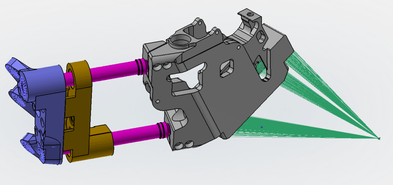
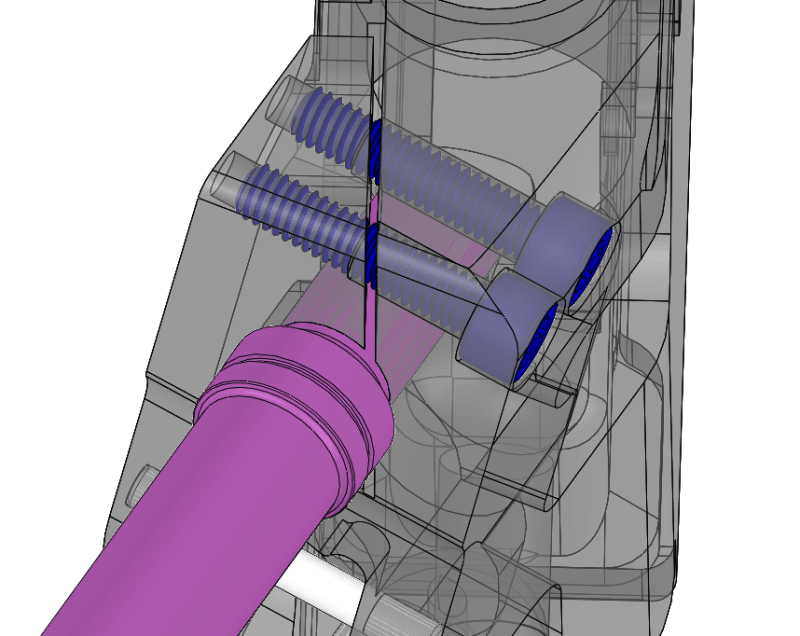
I am working on modeling an assembly where a shaft is held with a bolted split clamp.

I not sure what is the best way to simplify this connection in the FE model.

I currently have the parts set as bonded together, but I feel like that's not quite right. I am thinking instead of putting a really stiff CBUSH between the shaft (pink) and the clamp (grey), and then replacing the bolts across the split with equivalent springs.

Clamped_Geometry_c0xli8.png


But I am curious if anyone else has a better idea.

Also, I am using MSC Apex / Nastran for the modeling.
 
Replies continue below

Recommended for you

what loads are coming across the joint ? hopefully not fastener torsion ?

when the joint is fully tight, will the gap in the joint close up ?

is the radius of the hole slightly bigger than the shaft ?

"Hoffen wir mal, dass alles gut geht !"
General Paulus, Nov 1942, outside Stalingrad after the launch of Operation Uranus.
 
what loads are coming across the joint ? hopefully not fastener torsion ?
The loads across the joint should be mostly perpendicular to the axis of the shaft. There is no torsion in the shaft.

when the joint is fully tight, will the gap in the joint close up ?
is the radius of the hole slightly bigger than the shaft ?

Yes and no, (tolerances notwithstanding) the shaft and the hole fit line to line, so once the bolts are tightened there will be some tiny amount of closing of the gap.
 
so first define the purpose of the FEM.
then define what you intend to get out of the FEM relative to this clamped joint.
 
SWComposites said:
so first define the purpose of the FEM.
then define what you intend to get out of the FEM relative to this clamped joint.

So here is a more zoomed out picture. The lavender piece on the left is grounded with some CBUSHs and the grey piece is being loaded by those RBE2s. I am interested in the overall stiffness/deflection of the design, the bolt loads between the brown & lavender piece and some stresses in the gray piece.

Analysis_Setup_cayq3d.png


As far as the clamped joint is specifically concerned, I am not too interested in the it, but rather making sure that it is modelled in a way that doesn't add too much, or not enough, stiffness.

And really my question was meant to be a little more globally how do more experienced analysts handle simplifying clamp joints?
 
If you are interested in overall deflection, I would not bother trying to model the fasteners, assuming they are designed to be torqued up to provide clamp-up. For the clamp joints I would just tie the parts together; there shouldn't be much flexibility in those joints.
 
those split clamp joints look very "fussy". I suspect there are a mountain of detail issues with them, if not familiar with them you don't even know the issues !?

is this a common design feature for your company ? so they have alot of inside information about them.

me, I'd be worried about the tension in the bolts, what external loads cause tension in the bolts?

how critical is this detail ? will you be testing it ??

"Hoffen wir mal, dass alles gut geht !"
General Paulus, Nov 1942, outside Stalingrad after the launch of Operation Uranus.
 
Status
Not open for further replies.

Part and Inventory Search

Sponsor