Continue to Site

Eng-Tips is the largest engineering community on the Internet

Intelligent Work Forums for Engineering Professionals

  • Congratulations waross on being selected by the Eng-Tips community for having the most helpful posts in the forums last week. Way to Go!

Simply supported vs fixed bolted connections

Status
Not open for further replies.

jgrady

Mechanical
Jan 30, 2015
34
Mechanical engineer here...having some trouble wrapping my head around things.

Say for example you have a beam botted between columns with an end plate bolted connection.

My understanding is that these connections are typically designed as simply supporting, taking only shear load. I guess the reasoning being that the bolted connection will only resist as large of a moment was it can, and then the rest will be transferred to the beam? Since the distribution is unknown it is cheaper/easier to just size the beam to take the full moment and size the connection for shear. So does that mean the columns really only need to be designed for axial load?

I know mainly in this forum you are designing for static loads. Is this type of design only good for static loading? I assume in a fatigue situation you would not want the bolted connection loaded to that point. So in this case would you have to design the connection to resist the full moment?

 
Replies continue below

Recommended for you

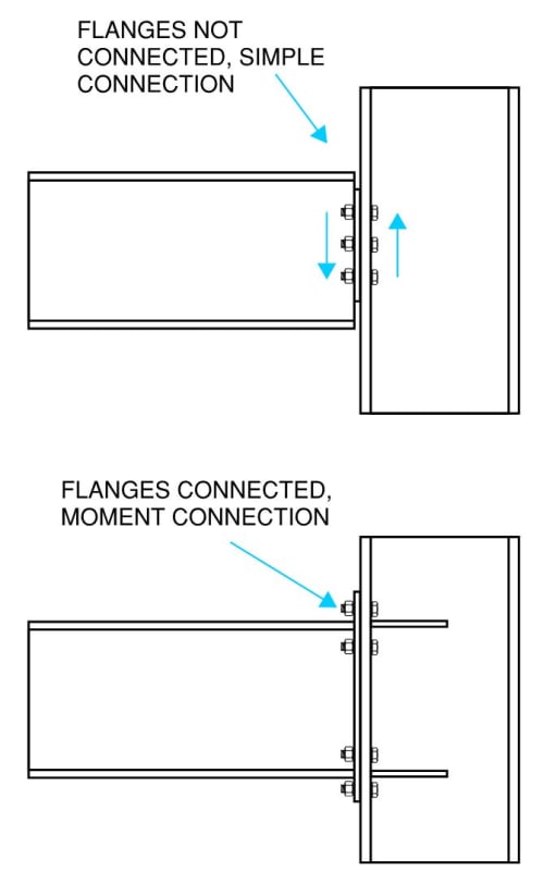
You typically have to provide continuity to the beam flanges to achieve a full fixity moment connection.

Capture_l9nphn.jpg


However, us structural engineers are usually concerned with the strength limit state, or how the member behaves at full capacity. At smaller force levels, such as vibration or fatigue, "simple" connections actually do exhibit rotational stiffness.
 
You have to take accidental bending into account for the column design but it is not usually done in a very precise manner since determining the moment at a "pin" connection is not easy. As a rule of thumb, some engineers will only stress the column to a maximum of 60 to 70% of code since accidental moment can quickly over-stress a steel column. If it has to be done a bit more precisely, I will usually take one half the width of the column plus the distance to the bolts plus about three or four inches to the inflection point. There are also papers available that help estimate the moment on the connection.

If I had a fatigue sensitive design, I would review the stresses caused by the bending at the "pin" support. You won't get the same moment as a fixed condition. You have to get the effective spring stiffness for the joint through experimental results or a very complex 3D FEA. Conservatively (especially if it is a one off design), you could over estimate the moment and the stresses and see if the design is still reasonable.

Simple support joint are used in steel buildings all the time that have to take seismic and wind loads. Although they wouldn't be used for the lateral resisting system, they will still receive accidental stresses. Elevators (machine support beams) and cranes have to use similar connections and these structures are definitely fatigue sensitive.
 
@cal91 @Earth314159

Even though it is fatigue, I am not talking about small loads in my case. Say you have a connection like the bottom scenario, the bolts still need to be sized to resist the full moment. If they are not then it will still be considered a pinned connection correct (well, somewhere in between technicaly)? Say the connection is repeatedly loaded past its point of rigidity, does this not mean that the bolts are going to be highly loaded? This is where my concern for fatigue comes from.

Won't we still end up with some variation of this scenario:

I guess what I am saying is that the entire structure is designed to take some loading, how the moments are distributed between the beam and connections are unknown. But if the connections are not sized to take the full moment, it seems to me like it is possible the bolts will be being stress beyond their fatigue limit.
 
Jgrady,

I would say if you are detailing the connection per the bottom scenario, you are designing as a moment connection and it should be sized and detailed accordingly. I don't know which code you are using but our code gives the maximum tensile stress difference and the acceptable number of cycles for different configurations of welds. This would definitely be a required check when there are large numbers of cycles and a high differential tensile stresses.

It is possible for a shear connection to be too rigid and attract unwanted bending. This can also lead to fatigue failures. I would say, the main problem is going halfway in between rigid and pin and designing the connection as a pin. If you design as a pin in a critical case, you should calculate a reasonable accidental moment and check the differential tensile stresses. The other option is to deliberately go full moment and keep the differential tensile stresses within the acceptable range.

If you have large moments (assuming you go that way), you also need to check the shear panel at the intersection of the two elements. You will get a high shear in the panel and accordingly high tensile stresses.
 
Status
Not open for further replies.

Part and Inventory Search

Sponsor