Continue to Site

Eng-Tips is the largest engineering community on the Internet

Intelligent Work Forums for Engineering Professionals

  • Congratulations IDS on being selected by the Eng-Tips community for having the most helpful posts in the forums last week. Way to Go!

Simulated load on 6.6kv generator 1

Status
Not open for further replies.

BEHC

Electrical
Jan 3, 2021
3
Nice little problem for you al1!

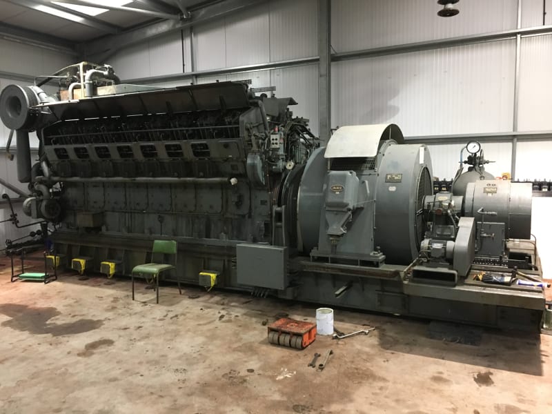
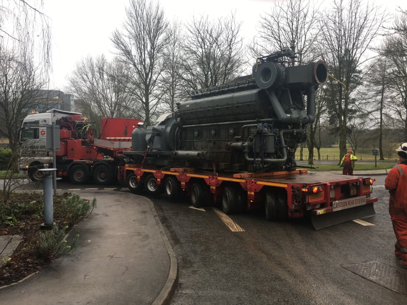
We have a 1965 British built by W H allen v16 large generating set that has just been saved for preservation. The complete set up is in very good condition having only done about 2600 hours. We have the complete contents of the generator building to include all the switchgear etc. This engine represents a British engine manufacturer and a early type of large packaged generator.

it also has open rocker gear which will be very nice to watch.

The alternator is a brushless type with the supply for the AVR being picked up via a 6.6kv/110volt voltage transformer. There must be an element of self exciting on start up?

The alternator was wired in star with the centre point earthed via a neutral resistor which we were unable to obtain due to asbestos content within the resistors housing.

The alternator details are

1666kva
1333kw
rpm 750
power factor 0.8
volts 6600
amps 145.7

Brushless a.c exciter details

kw (dc) 16.45
volts (dc) 82
amps (dc) 201
poles 6
3 phase
frequency 37.5
full load exciter ac voltage 49.4
ac current 6.13
rectifier connection. 3 phase bridge.

The engine is in perfect condition and within a few months this will be back fully operational after reconnecting the shut downs and control circuits which have been a total joy to work on due to their age.

I fully appreciate it is both impractical and unsafe to even think about returning the alternator to service plus to have the ability to load up this engine with a load bank, the resources involved and expenditure would be too great.

But...........

It would be good however, to place a load on this engine even if it is nowhere near to the full capacity of the alternator.

So here is the question: Thinking outside of the box do any of you think this alternator could be wired to give some sort of load.....such as windings shorted, d.c injection etc etc. basically anything that will cause a load to the prime mover without having to generate at the full voltage. I suppose the major problem is the flc current, as we reduce the voltage to a safe level the 145 odd amps on a 2000 hp diesel engine, it wont even know it is there! but I do not know about any other methods that could be used that are either used for testing purposes or a alternative radical approach.

Any ideas or do you think it is impractical and wont actually generate any sort of engine load,

I have attached some pictures of the generator that was saved, ironically from Astra Zenica early last year. Little did we know what was about to come.

Cheers

M
IMG_0581_rswalb.jpg
IMG_0588_voijfa.jpg
ark
 
Replies continue below

Recommended for you

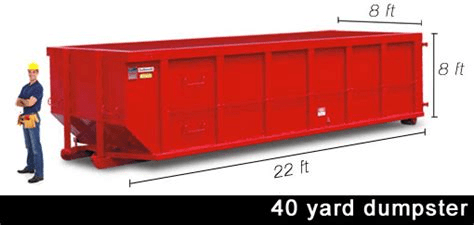
There is always the saltwater rheostat dumpster gambit. It would allow a full load or anything less. You would need to work out how to do it safely but I suspect it's possible with a little care and not a lot of money.

Keith Cress
kcress -
 
What Keith said.
Been there, done that, at 120/240 volts and 120/208 Volts.
I strongly suggest finding a transformer to drop the voltage down to under 600 Volts.
I needed a five day load test of a 350 KVA set to satisfy the vendor.
I used six, 50 Gallon, plastic barrels, two per phase.
My electrodes were truck leaf springs from a wrecking yard.
It worked well.
Search this site for more details.
image_rdvrqp.png

image_rizryj.png

4 YARD DUMPSTER
Plan on adding a lot of make-up water.
100 kW will boil off about 30 gallons per hour.
You may consider sharing your plans with the local fire company, lest some passer by mistakes the clouds of water vapour for smoke and calls in an alarm.
(There's a story behind that as well.)

Bill
--------------------
"Why not the best?"
Jimmy Carter
 
If your budget is as weak as I suspect, try this:
Disconnect the AVR.
Power the brushless exciter with a variable voltage DC power supply.
The input to the brushless exciter should be much less than the 16.45 Output.
Set up your dumpsters with scrap iron electrodes.
Start the engine and slowly ramp up the excitation, while monitoring the current.
If you have enough electrode surface and enough salt in the water, at 220 Volts to ground you may be able to generate about 90 KW.

Bill
--------------------
"Why not the best?"
Jimmy Carter
 
Interesting project!

Did you get the radiator or cooling tower as well? The you need fuel and lube oil tanks and all the pipework, exhaust silencer etc? You seem to have the airstart system, as I can see the cylinder on the far side of the engine.

Where is it being installed?

The generator (correct term for alternator) is AEI. They were at Mill Road Rugby and were integrated into UK General Electric Company (no connection to the US company) in the late 1960's after Arnold Weinstock's amalgamation of GEC, English Electric and AEI.

I see a belt driven small 'motor' at the side of the main exciter? Is this actually a pilot exciter?

With this size of set, the AVR often went in the 6.6kv switchgear.

After several changes of ownership, AEI eventually became part of ... US General Electric! I think that the Rugby site has been closed and moved to Nancy in France.

WH Allen were part of APE which became part of NEI (Formed from Reyrolle Parsons), then bought by Rolls Royce.
Eventually Allens were closed and the spares repairs etc went into a new company Allen Diesels: I think that this engine will be a type S12.

I think that you will have to register this set under the Medium Combustion Plant Directive and will need a permit, if you ever run it.

Its a complex area:
As others have said, you may be able to engineer a 'wet' load bank.

This age of set would almost certainly have mechanical governor, so not much in the way of controls. To start the engine you just walk round and pull the levers on the hand starters for fans and pumps, then turn the air start lever on the engine and off she goes!

Good luck!
 
some sort of load.....such as windings shorted,
Been there, done that as well.
A 350 KVA set that was water saturated and needed to be dried out. (480 Volts)
We shorted the windings and excited the field with a battery charger.
That was enough to drive about 50% current through the windings.
It worked but took three or four days to dry the set.
50% current at almost zero Volts is not very many Watts.
I doubt that you will detect any difference in the engine operation when it picks up this load.

By the way, is the small belt driven machine an Amplidyne to amplify the output of the AVR to drive the exciter?

Bill
--------------------
"Why not the best?"
Jimmy Carter
 
Well thanks for all the excellent replies!

Hoxton123, in relation to your questions.....yes,yes and yes.

You win ten points, it is in fact a S12 engine, a VBCS12C 16 cylinder to be precise.

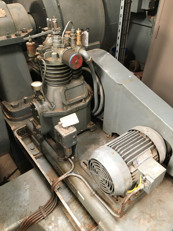
The engine is a complete packaged set so the thing that could be a small separate exciter is in fact the belt driven air start compressor, it also had (until it got nicked) a small diesel driven compressor bolted to the skid should it had to start in a complete black out with no air in the receiver.

On the other side of the engine are the coolers. we obtained the exhaust system and the fuel oil booster pumps and day tank etc.

I was unable to get the external cooling tower but I have a 400kv wall bushing that I am going to mount vertical outside in its own small pool and pump the raw water up the centre to cascade over the top and down the sides of the insulator. As this engine will only run for fun I doubt we will even need any major cooling as the fresh water circuit is so large that it will probably do most of the cooling until the raw water is required.

The governor is mechanical being the famous woodward UG type.

The engine is nearly piped up and all we need to do is double check crankshaft deflections and fit the exhaust silencer after casting a suitable external concrete slab to mount it.

I feel this engine may never get suitably loaded as even though I don't mind the odd risk, the words 1.3 megawatt (with the associated fault currents), 2000 hp prime mover, electrodes, dumpster skips, ability for 6.6kv and finally salt water.......it could go very wrong very quickly and it would not be a spark it would be a large explosion!!

The AVR and control gear did get its supply from the 6.6kv voltage transformer but interestingly it had a separate supply from a single C.T that was located in the single cable that came from the star connection to the earthing resistor....the idea being that during a major earth fault within the generator or external, the V.T would have the potential for reduced voltage as the fault could either cause the voltage to collapse or the fault was internal to the windings but the fault current via the centre point of the star connection via earth could be carrying a very large fault current but at a low voltage. It would be this current that would in turn generate voltage in the C.t to enable circuit protection to operate etc.....if you get what I mean with my basic explanation.

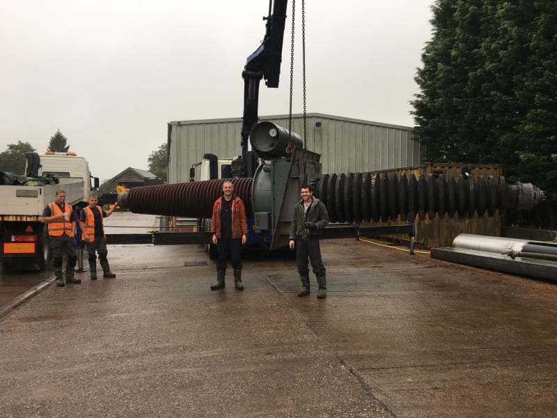
I have attached some pictures of the belt driven compressor and the insulator I want to strip down to get the portion that was sat inside of the building with the insulator "sheds" that will be pointing upwards when it is installed vertical as my novelty cooling tower. Basically the cleaner portion of the wall bushing.

IMG_0590_xmo1uj.jpg
IMG_0926_cjyqlg.jpg
IMG_0394_wcyc5h.jpg
 
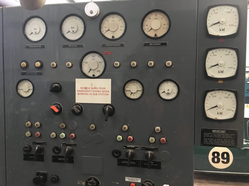
I love the meters in the control panel.
Here in the US we can get a 6yd dumpster that is heavy plastic in a steel frame. 1000 gal is a lot of water.
We used on for such a load test in the past. And yes were used externa voltage control since we only needed about 35% load for the testing.
You can make these pretty safe if you limit the voltage.

= = = = = = = = = = = = = = = = = = = =
P.E. Metallurgy, consulting work welcomed
 
The CT was for excitation support in the event of a major fault. It avoided voltage collapse when the fault dragged the terminal voltage down.
These were common before PMGs became common.
There was another excitation that used a constant voltage transformer to provide no load excitation.
A load CT output was dropped across a resistor and rectified and fed to the field to increase the excitation proportionally to load increases. The load compensation could be adjusted by sliding the tap on an adjustable wire wound resistor.
This had the advantage that it was fairly easy to overexcite slightly under load to compensate for line drops on long feeders.
The basic constant voltage transformer and CT were great for isolated third world sets.
The only semiconductor was a simple bridge rectifier.
I have also seen one providing 5% voltage regulation with a conventional AVR fitted to improve the regulation to 1% or 2%.
Should the AVR fail the set could continue in service with 5% regulation. (Government job.)

Bill
--------------------
"Why not the best?"
Jimmy Carter
 
Interesting, I asked the question here in the past. Delco used to call it a triple action booster.


But, I figured out that it was used to boost field current as output voltage dropped. Better regulators eliminated the need. Then, PMG solved many problems but had not fully caught on yet.

PMG is awesome for reasons I'll tell you if you want to know.

FYI, waross will confirm, your generator will make voltage even without the AVR connected. There is typically enough residual magnetism to generate some voltage. Many AVRs actually use this to start themselves. If voltage is insufficient a field flash is done by running a few lantern batteries through the gen windings prior to a start.

To waross, I have since installed Basler AVC63 regulators in this panel and they do not require boosters. You were very helpful in this decision.
 
When a generator suffers a close in fault, the voltage is pulled down.
The old voltage regulators that were powered from the generator output (and bootstrapped themselves with the residual magnetism) would not get enough power from the dropped terminal voltage to fully excite the field.
With an under-excited field the voltage would drop further.
As the voltage dropped, the current dropped.
With the terminal voltage close to zero, and a short on the output, the I2R would be quite low and the engine would unload.
If the protection didn't go out instantaneously, there would not be enough current to cause an inverse time trip.
The solution was a CT powered boost to increase fault current to ensure dependable operation of the protection circuits.
This was not to be confused with the other system that I mentioned were a CT and a constant voltage transformer were used together to provide voltage regulation.
Hey, If my rambling discourses are boring anyone I will try to curtail myself a little. (Results not guaranteed. grin)

Bill
--------------------
"Why not the best?"
Jimmy Carter
 
Thanks BEHC for your reply.
So you are going for an 'open' cooling system...

A few potential problems
Contamination from leaves, dead birds, frogs etc
Corrosion - if using plain water it should be de-ionised or distilled etc, then an inhibitor added to prevent corrosion.
Freezing, add glycol or keep the water warm if using plain water.

You may be ok with an open water circuit, but it depends how long you want to keep your engine!

A 'marine' engine has water in a closed circuit, through the engine, then back through a heat exchanger. The other side of the heat exchanger is (raw) sea water. There will be a marine version of this engine, so someone may have a schematic. You need a pump on the sea water side. A marine engine has two engine driven pumps (possibly three if the engine has an intercooler).

One peculiarity of Allen engines was that the ones I knew used a two bearing generator. Mirrlees, Blackstone, Ruston, MWM etc generally used a single bearing generator, with the bearing at the exciter end of the generator.

The drive end of the generator had a flange which was bolted to the engine flange with no flexible coupling.
 
There was still a flexible coupling, the flange on the generator rotor consisted of many thin sheets of metal which allows it to flex.

As for the water, I not only agree but any to emphasize that it is imperative that you don't put water in the engine. It's called coolant, not water. Coolant has corrosion inhibitors. If you want to go cheap, you can treat the water with any 2000 series diesel engine supplemental coolant additive at 16;1 for straight water and 32:1 for 50/50.
 
Sorry, the mirrlees etc sets were solidly coupled, not flexibly. Generally the larger generators had a forged shaft with integral drive flange.

You are correct about the terminology, it is correct to refer to the fluid as coolant, not water, my slip.

We used to buy pre-mixed coolant, because you must not use tap water, or worse river water. .

if you use glycol your heat exchangers etc must be about 30% larger, so its tempting to find a way not to use it.

 
I wasn't trying to correct you. I just work in an industry that doesn't understand the importance of cooling water treatment so I always make that emphasis.

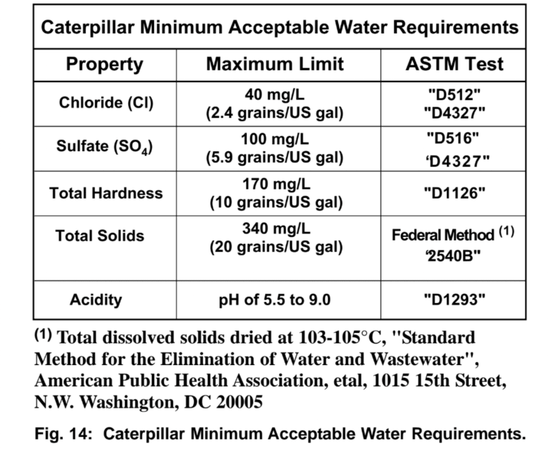
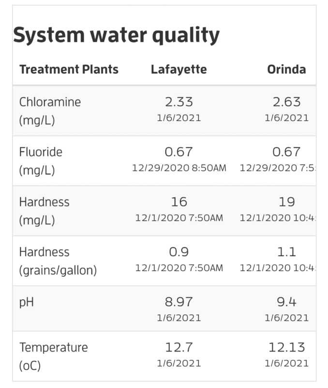
Tap water does work fine provided it meets certain requirements. We have really good tap water out here.

Required:
Screenshot_20210107-102308_pbd5rn.png


Delivered:

Screenshot_20210107-102331_avth24.png
 
In relation to cooling, this engine does have two circuits. One is raw and the other is fresh. I have reinstated the fresh water cooling system and this has been refilled with treated water and the system dosed with a feedwater company additive suitable for medium speed diesels.

The raw water system that I want to use with the external crude cooling tower serves the fresh water and oil coolers plus the charge air cooler.

I can drain this raw water down every time after use as I can imagine I will only be running the engine for demonstration purposes. I can keep the reservoir clean and have a strainer for the dead frogs!!

This raw water will only be passing through the tube coolers/ charge air cooler such as sea water as found on a vessel.

On the free end of the engine is two engine driven circulation pumps, one for the fresh water circuit and the other for the raw water circuit.

Talking mirrlees, most of my time was with K6 majors plus MB275's and I have a picture somewhere with a K6 that has a leg out of bed as they say, its the damage to the steel work in the engineroom that is impressive not the failed rod! I also had one run away as the service exchange blowers shaft seal failed after two days, this was fed from the main engine oil circuit so instead of having just a small turbo charger sump to go at.....it had access to the several thousand litres in the main engines dry sump which it did it best at burning whilst we were trying to stop it. She stopped as we were about to bulk flood the engineroom with co2 as we found out later the valve gear had started to fail.

This engine had a 1.8 mega watt shaft alternator on the free end driving a very large dredge pump (the drive end drove the vessels CPP propeller via a reduction gearbox. The soft start had failed years ago so the start procedure was to knock the excitation off, close the breaker, turn the excitation back on and and stand back as the poor engine was on its arse. The VSD was built in 1986 and weighed about 7 tons but when it failed in the mid 1990's they could not find anyone to fix it. After a while all four fitted to the four sister class of dredgers failed. When dredging the ships power was transferred to an aux generator and some very basic speed control was offered by allowing the bridge to alter the main engine speed very slightly.

These had separate electrically driven cooling pumps for both raw and fresh water circuits and a small third pump for the valve cages, my main problems were issues with cracked valve cages and separate VCC cooling flexible hoses but these were supplied non genuine by the company to try and keep costs down so what do you expect. The only engine driven pump was the lube oil pump.

The slow speed B and W engines I worked with, no cooling water issues at all other than the odd pump shaft seal.

Thanks again for the time for you to all comment.


I've never seen stationary engine with a raw water pump before. I wonder what makes this one unique.

Anyways, I believe I see an aftercooler under the turbos. The engine won't be producing any boost so there will be plenty of cool air flowing through them. Just plumb the jacket water through the aftercoolers and voila, cooling system.

You could also use a radiator from a highway truck. The heat rate is equal to the power produced by the engine so that would be good enough up to a few hundred KW.

 
Status
Not open for further replies.

Part and Inventory Search

Sponsor