Continue to Site

Eng-Tips is the largest engineering community on the Internet

Intelligent Work Forums for Engineering Professionals

  • Congratulations KootK on being selected by the Eng-Tips community for having the most helpful posts in the forums last week. Way to Go!

simulation of edge bending

Status
Not open for further replies.

FEA_User

Automotive
Jan 27, 2022
27
Hello all,
i'm trying to simulate the edge bending of sheet metal using deck abaqus in ANSA but the calculation still diverging,
the error is related to the contact pair "the stimated contact force error is outside of convergence tolerance"
what could be the problem please?


or who can build me a quick model
thanks in advance
 
 https://files.engineering.com/getfile.aspx?folder=1ca8a9de-6520-44b5-920e-66eabaadc404&file=Capture_d'écran_2024-04-10_182206.jpg
Replies continue below

Recommended for you

HELLO.
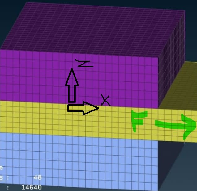
the yellow part is in contact pair with the top and bottom parts, and it defined as a rigid body
i want to find the "pull out" force F (green arrow) if i apply 5G load (gravity)
1- is it possible to do this simulation with dynamic explicit analysis?
2- what is the right output to find this force? what's about the RF in the master node of rigid body?
3- if th 5G gravity LOAD is in Z direction , is the force = 0 or we still have a tangential forces?? What is the output to get this tangential force?
4- are RF 1,2,3 the reaction forces in the directions X,Y and Z ?

up_ihmk8j.jpg


thanks in advance
 
1 - yes
2 - if you pull the yellow part by applying a prescribed displacement BC to the reference node of a rigid body associated with the part then RF will be the reaction opposing that pull
3 - tangential forces will appear if you define friction for contact, the output can be CFS if you want the total tangential force as a history output
4 - yes
 
@ Fea way: thanks again for your support
1-I will apply the gravity acceleration to all component not on the master node of the rigid body so is it correct thar the reaction force measured at the master node of RB at X direction = force F ?
2-if i'm right, if the gravity load is in Z direction F should be 0 F=0
 
If you want to determine the pull-out force when gravity load is acting in the perpendicular direction, you have to actually pull that part by applying a prescribed displacement BC to it. Otherwise, there will be no motion in the tangential direction, you will only have pressure in contact from gravity.
 
Hello;
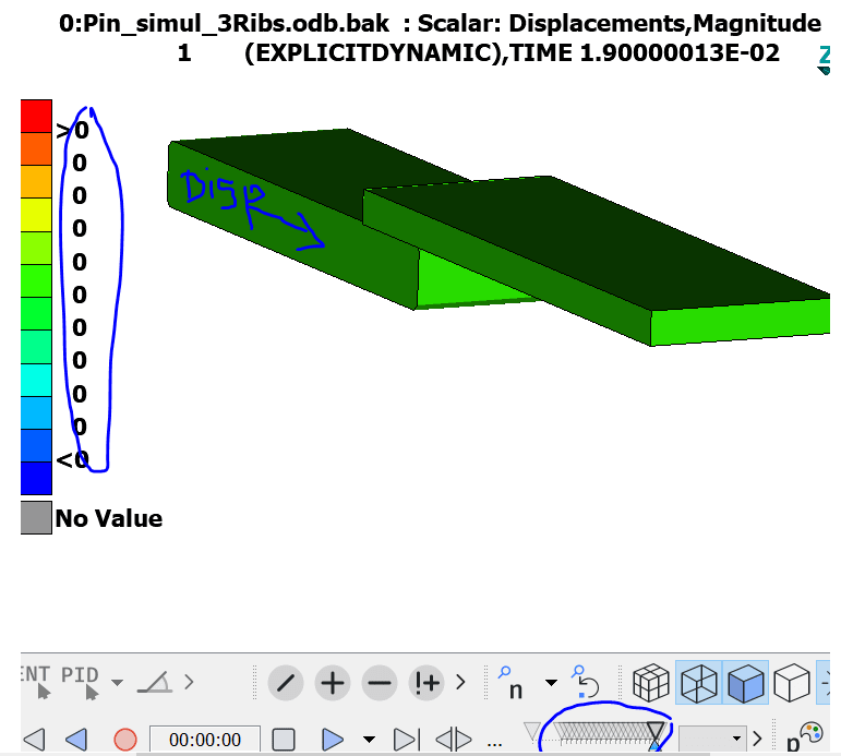
Please for the previous Explicit dynamic analysis,i tried to apply a (BC) displacement of 28mm instead of the (cload) force. The part doesn't move until the end of the step!
Can we use a displacement BC in explicit dynamic analysis?
 
Yes, prescribed displacement BCs can be used in explicit dynamics but they must have an amplitude assigned. Preferably one with smooth changes if it's a quasi-static problem but regular ramp amplitude is often used too.
 
Hello;
thanks again for your support!
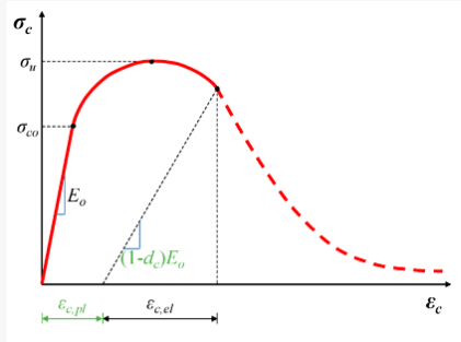
please how can I use one or more of those terms to define the fatigue behavior with abaqus:
1- "strain energy density"
2- "Freudenthal criteria" and if it possible to implement the formula into abaqus or using it with some output :
Picture1_awlxxt.png

3- is there a direct output to define the fatigue factor?
thanks in advance
 
Elastic strain energy density is available as the SENER output variable. For the rest of this you will need custom calculations.
 
@ FEA way thanks again for your Help!
is there an equivalent output of SENER which cover the plastic domain too?
grafff_pd3emp.png

and what's about PE and PEEQ outputs?
 
PENER - energy dissipated by plasticity per unit volume

PE and PEEQ are just plastic strain components and equivalent plastic strain, respectively.
 
Hello;
thanks again for your support!
i tried to use a BC displacement in order to move the cube in Z direction but it still not moving until the end of the time step! the same analysis works with a cload force.
zzz_bvyje6.png

*********************************************************************************************
AAAAA_hl88na.png


i joined the inp file
thanks for help
 
Don't apply instantaneous amplitude for a displacement boundary condition in Explicit, use ramp amplitude instead.
 
Can you delete this last reply and start a new thread since it's a completely different model (motor rotor?) ?
 
Hello, thanks for your support
I still not able to run this analysis with displacement BC instead of force!
Ramp amplitude is not supported by abaqus explicit
Please who can provide me with an exemple of a working inp for explicit analysis using an imposed displacement BC.
 
I wasn't talking about the built-in Ramp amplitude type but about manually defined amplitude of this shape. Just something like this:
t A
0 0
1 1
 
Status
Not open for further replies.

Part and Inventory Search

Sponsor