Continue to Site

Eng-Tips is the largest engineering community on the Internet

Intelligent Work Forums for Engineering Professionals

  • Congratulations SDETERS on being selected by the Eng-Tips community for having the most helpful posts in the forums last week. Way to Go!

Simultaneous position and establishing a clocking datum 1

Status
Not open for further replies.

sendithard

Industrial
Aug 26, 2021
186
I've got so many questions on this callout that it is better to ask questions over several posts Apologies for the rambling. The part I have is somewhat like the below picture. It is two less than half spherical cutouts inside a part. Disregard the idea of a feature of size as everything under the sun here is a fos.

The callout is simultaneous as the spheres are located basic to each other(and with same DRF) and then to the bore axis(datum A) and the bottom plane(Datum B):
0.05mm A|B so this is a spherical position callout located to the bore axis and a basic dimension to the bottom plane.

Our engineering team requires two positional outputs separately. So if the spheres are 6mm basic apart...We in essence are measuring them 3mm from the axis.

1) If you measure them separately...and they pass, does that mean they will pass simultaneously?
a) I played around in CAD with a 4 hole pattern and I couldn't really come up with a scenario where if they all pass individually, they would somehow fail together. This is where my lack of experience makes me question all my thoughts on this​

2) The clocking datum is not arrested so I am thinking about using the midpoint of the spheres as the clocking XY datum plane creation.
a) this would mean the spheres could be crooked compared to the rectangle nature of the part, but does this strategy creatively measure them simulteneously while still outputting them individually?​

3) Alternatively, if I use a midplane of the part as the clocking datum this would keep the sphere more true to the overall part, but then does that violate the simultaneous theory of the standard?

I'm a little confused here so I appreciate the guidance. I will be discussing with our overall leader soon, but I wanted to get your thoughts before I ask for a meeting. Functionality, and eliminating assembly errors trumps everything, but I'm asking for a technical take on the GDT and perhaps personal opinions.
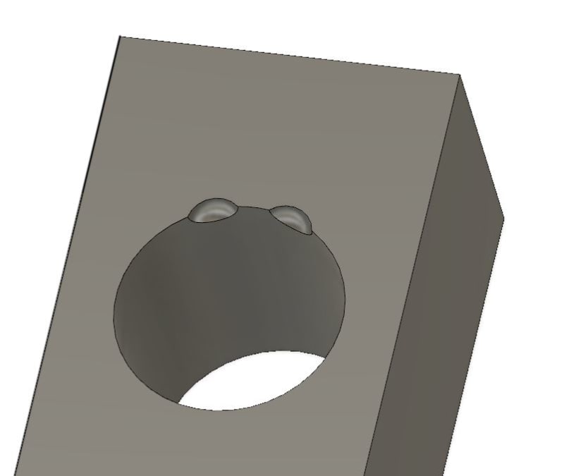
Capture_pdk8tq.jpg
 
Replies continue below

Recommended for you

Hi, sendithard:

You did not say how to locate these two features. Are you trying to use "Position" to control them? A partial spherical surface is not a feature of size. Therefore, you should not use a "Position" feature control for them if that is in your mind. A good feature control is a profile of surfaces. If you have a tighter tolerance between them, you will need to a composite profile.

Best regards,

Alex

 
sendithard,

I understand that you said that we should think about the spherical features as if they are FOS, but just for the record I need to say they are not FOS and as such should not be controlled with position tolerancing.

Putting this aside, if both features are defined relative to A|B, they shall be considered a pattern, therefore shall be inspected as such. This does not mean you can't measure them separately, however you need to respect the constraints imposed by the simultaneous requirements rule when doing so.

The |A|B| reference will not control rotation/clocking of the pattern of two relative to the width of the block, unless the width is also controlled with a tolerance to |A|B| or is defined as datum feature C and then referenced tertiary in the geometric callout for the spheres.
 
1) If datum shift is allowed they could pass independently if each requires a separate datum shift to do so. This may include part rocking on planar datum features or repositioning for FOS datum features with MMB/LMB reference modifiers.

2, 3) The CMM software should do the fit without any clocking reference.

Lacking any information about mating features/parts/expectations - we can't tell about functionality or errors from your description. Your engineers should have generated a tolerance analysis explaining their decisions.
 
3DDave said:
1) If datum shift is allowed they could pass independently if each requires a separate datum shift to do so. This may include part rocking on planar datum features or repositioning for FOS datum features with MMB/LMB reference modifiers.

sendithard said:
0.05mm A|B so this is a spherical position callout located to the bore axis and a basic dimension to the bottom plane.
 
I'm not making decisions based on what you all say so you don't have to worry about a plane falling out of the sky..these parts are not affecting people.


There is no datum shift here.

Let me back up a second and ask a very simple question.....

If a 4 hole square pattern is called out to a central bore axis positionally...each hole is 6mm basic from each other, but the primary datum is the bored axis....could you output each separately as 3mm from the bored axis and be assured if all 4 holes pass individually they each pass as a group(simultaneously)?
 
3d Dave...pcdmis(CMM) depending on which version you use requires a clocking datum. The older version will best fit to output a minimized positional measurement, but as indicated you could have those spheres crooked to the rectangle nature of the part and pass...it is probably intended to have those spheres true to the rectangle nature of the part but my question is if I output both spheres independently based on the midplane of the part width could they pass individually and somehow fail simultaneously?


Im not using pcdmis but we have 4 cmms that use it. Im experience in that CMM software but using GOM now...same thing...you can underdefine the clocking and get a best fit if you want....or fully define to better output XY for offsets
 
sendithard said:
If a 4 hole square pattern is called out to a central bore axis positionally...each hole is 6mm basic from each other, but the primary datum is the bored axis....could you output each separately as 3mm from the bored axis and be assured if all 4 holes pass individually they each pass as a group(simultaneously)?

If they are all measured in the same setup (i.e., the part does not get rotated about the datum axis between the individual hole position measurements), as they should per the simultaneous requirements rule, then they must pass as a group as well.
 
pmarc,

The width doesn't need to be held back to AB...it's midplane technically only would be able to be controlled to A(the axis) as to B you can't establish a distance.


The clocking width midplane only would force the line between both spheres center pnt to be perpendicular to some degree to the left-right sides midplane...it trues up both spheres to the overall part. I'm not convinced doing this allows both to pass independently and pass simultaneously...i feel you must orient the clocking to the midpoint of each sphere to do so...but at a cost that both spheres as a pattern could be spun around with no angular relationship to either midplane
 
pmarc,


Yea my in theory question about 4 holes basic to each other but measured independently resides with ONE setup...

If they all passed the inherent distance from the center axis in one fully defined setup, then the pattern should pass correct?
 
pmarc - when dealing with a user who doesn't know HOW such a condition could possibly occur, it is useful to explain HOW such a condition could possibly occur, even if this single specific case doesn't yet get changed.

It should all be in the design analysis from the engineers.

I doubt very much the mating part is a plate with a perfectly perpendicular expanding pin, so the requirements are suspect to begin with.

A square 6mm pattern? Each hole cannot nominally be 3mm from the axis.
 
sendithard,
Help me out here as I am still a little bit concerned that not everything is clear to me from your description and that my previous answer may be misleading. In your "measured independently" 4-hole scenario, what are you exacly measuring? Is it only 4 times the individual distance between the datum axis and each hole axis?
 
"3d Dave...pcdmis(CMM) depending on which version you use requires a clocking datum."

Yes, and older machines did not even have pcdmis so the user had to make repeated tweaks by hand to the part alignment relative to the machine axes until they found it passed or they gave up or asked engineering for a design change.

A pcdmis forum could help with pcdmis problems.
 
Hi, sendithard:

"Center" of a partial spherical surface is called "ill - condition" according to math or numerical analysis. That is why ASME Y14.5 treats it not as a feature of size. To report distances of a partial spherical features is a bad idea because it is not stable.

Best regards,

Alex
 
pmarc,

Thanks for asking for clarity.

Lets say there are 4 half spheres cutout instead of the 2 in my picture. They are all 6mm from each other basic. And lets say the print added the clocking datum width of the part...so it would be a 0.05mm ABC fully constrained setup.


If the main datum is the Bore, then can you measure each independently using basically a 3mm basic and know that if each pass independently that they will pass as a pattern.

When you see 4x positional callout at 0.05mm ABC can you measure each independently from the primary axis with the same clocking datum and be assured they pass as a group to the same 0.05mm ABC setup.

Sounds like you are saying if they pass individually they pass as a pattern.
 
Alex,

I'd pay you $1000 to save me from this problem...im well aware I don't have a fos...half my day consists of tricking software from non fos to a constructed fos so I can trick the software into giving me bonus.


If you want me to give you a list if companies to email about how bad their GDT is let me know.
 
sendithard said:
When you see 4x positional callout at 0.05mm ABC can you measure each independently from the primary axis with the same clocking datum and be assured they pass as a group to the same 0.05mm ABC setup.

Sounds like you are saying if they pass individually they pass as a pattern.

Yes, that's what I am saying.
 
Hi, sendithard:

The problem does not exist. The reason you have this issue is that you insist on FOS (feature of size) for a non-FOS.

If you have three persons standing on the ground, in principle, you can determine center of "The earth" if you know positions of each person. But in reality, it doesn't work because it is "ill - conditioned". The three persons are not separated far enough. This is foundation for FOS.

Best regards,

Alex
 
"ASME Y14.5 treats it not as a feature of size."

ASME Y14.5 doesn't include any information on excluding partial features as FOS. They even added partial feature examples based on the "irregular" FOS.
 
"half my day consists of tricking software from non fos to a constructed fos so I can trick the software into giving me bonus."

So you don't know what they really want, they don't know what they really want, so what is the point of performing an inspection that has ambiguous results, besides a paycheck?

I presume the company you work for doesn't care what errors there are in the requirements as long as they get paid and they depend on you to sell off the parts by making sure they pass inspection. If the given requirements make no sense, generate some other requirements that do.

Including an inspection plan with the bid would go a long way, but I bet that would risk the purchasing company rep noting that other companies appear to understand the requirements as-is and can proceed without a plan. No one wants to point out the Emperor has no clothes. Or the cost to generate a plan on all bids is unacceptable due to a low selection rate. Or it would allow customers to take that plan to some competitor that had trouble figuring out what to do.

Seems like a lot of contractual suck all around; a people problem rather than a Y14.5 problem.
 
Status
Not open for further replies.

Part and Inventory Search

Sponsor