Hello,
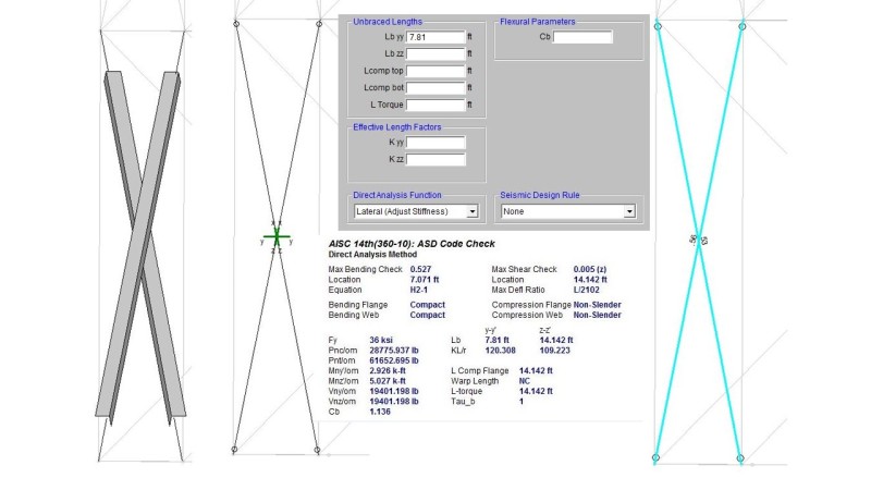
I've run into a situation in RISA that has me confused. This could be a dumb question as I'm relatively new to the software. I'm designing an x-braced frame for a piece of equipment. I would like set the members to “Both Ways.” I'm using single equal leg angles as diagonal x-bracing. I have out of plane loads along with axial loads. I understand that RISA uses the principal axes for the bending unity check. I also know that I can force it to use the geometric axes by setting LcompTop/LcompBot to 0.
My angles will be oriented with the vertical leg pointing down. Graphically this can be drawn 2 ways. I can set the x-axis rotation to either 90 or 180. This results in either the local y or local z axis, respectively, sticking out of plane. I get different unity check results depending on which orientation I choose. I believe, this is due to the orientation of the y' and z' principal axes.
I could figure out which orientation (90 or 180) is more conservative and go with that but is that overly conservative considering my angle is actually 45 degrees off from the worst case principal axis orientation? It also made me question my unbraced length assumptions.
If the angle is oriented with the local z sticking out of plane, I am considering the member is braced by the other diagonal from buckling about local z axis but not braced out of plane (about the y axis). Thus Lbyy would be full length and Lbzz would be 0.5 length. With this line of thought, the opposite should be true if I set it up with the local y axis sticking out.
Local z-axis out of plane:
Lbyy = Full Length
Lbzz = 0.5 Length
Local y-axis out of plane:
Lbyy = 0.5 Length
Lbzz = Full Length
However, if is Lbyy is actually Lbyy’ and Lbzz is actually Lbzz’, the other diagonal does not actually align with a principal axis so I’m not sure how to specify unbraced lengths??? The other diagonal lines up with the geometric axis and not the principal axis.
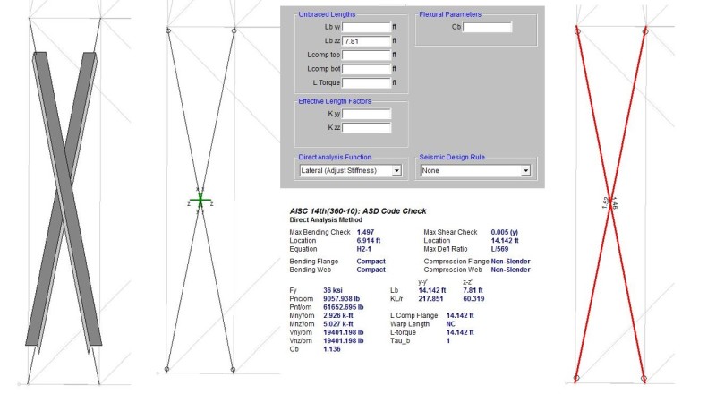