Continue to Site

Eng-Tips is the largest engineering community on the Internet

Intelligent Work Forums for Engineering Professionals

  • Congratulations KootK on being selected by the Eng-Tips community for having the most helpful posts in the forums last week. Way to Go!

Single-bolt bracing connection

Status
Not open for further replies.

bugbus

Structural
Aug 14, 2018
502
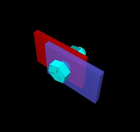
Refer below picture.

This is a connection for a bracing member (tension-only tie rod). The applicable design code (AS5100) states that bolted connections shall have at least 2 bolts, except in case of light bracing members (which this certainly is covered by).

A single M20 bolt satisfies the design loading with about 80% utilisation assuming pure shear in the bolt. The plates are 75x10 mm thick and loaded in pure tension.

Are there any additional bending/prying effects that need to be considered here? No doubt the plates will bend and rotate slightly under tension and the bolt will experience some combined shear and tension. But I'm not sure if this is significant or worth worrying about.
Capture_fokxco.jpg
 
Replies continue below

Recommended for you

Don't like single bolt connections, even if code technically allows them. Is there a compelling reason you can't just add a second bolt?
 
It's possible but might cause some problems for installation. Main advantage of the single bolt is getting the tie rods to align, since these are all at odd angles.
 
AS 4100 Supp1 states the following references for evaluating prying:

1 Hogan, T.J., and Thomas, I.R., Design of Structural Connections, Australian Institute of Steel Construction, Fourth Edition, 1994.
2 Australian Institute of Steel Construction, Standardized Structural Connections, AISC, Fourth Edition, 1998.
3 Woolcock, S.T., and Kitipornchai, S., ‘Tension Members and Self Weight’, Steel Construction, Australian Institute of Steel Construction, Vol. 19, No.1, 1985.
4 Kulak, G.L., Fisher, J.W., and Struik, J.H.A., Guide to Design Criteria for Bolted and Rivetted Joints, John Wiley, Second Edition, 1987.
 
Does the AS code have a formula that addresses eccentricity? Can you post it?

Rather than think climate change and the corona virus as science, think of it as the wrath of God. Feel any better?

-Dik
 
Yes, you are correct the eccentricity of the connection will be 1/2*tp1+1/2*tp2.

I think you could increase the edge distance to counter act the "torsion" type moment.

Just draw the FBD and design for the prying action and shear-tension.

Make sure you design the plates for the weak axis bending from that "torsion" and check the bearing / tearout
 
80% utilisation is not where I like to live for the sake of avoiding an extra bolt. Like others have said there is prying involved here.

For both economical and laziness reasons I would just throw a second bolt in there and call it a day. Unless this connection is being used in 100++ times over the course of a building then the economies are not there. (As part of a design and build firm where bonuses are paid on builds under budget I have plenty of incentive for economic design, more so than many structural engineers.) But I find it better to focus my efforts on the bigger picture stuff.
 
Let it yield the first time... then it behaves elastically up to that load... limit load is still the same...

Rather than think climate change and the corona virus as science, think of it as the wrath of God. Feel any better?

-Dik
 
I don't imagine there's a convenient way to make one side of of the joint into a clevis? Loading the pin in double shear would eliminate the local eccentricity.

Ultimately the numbers should dictate the design. If you have major doubts about the analysis, and no design code or some kind of precedent to back you up, test it or else change it.
In my universe, durability of this kind of joint would also be a consideration, due to cyclic loading and the materials we use. However I assume your main concern would be static strength.
 
Status
Not open for further replies.

Part and Inventory Search

Sponsor