KubusKubus
Structural
- Nov 12, 2017
- 8
Dear All,
As per bs5950-1-1990-structural-steel-hot-rolled.pdf - single fillet weld should not be subjected to bending.
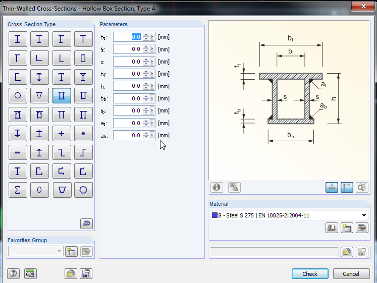
But I can see in that rectangular build-up hollow section is allowed to be used - webs are welded as single fillet weld.
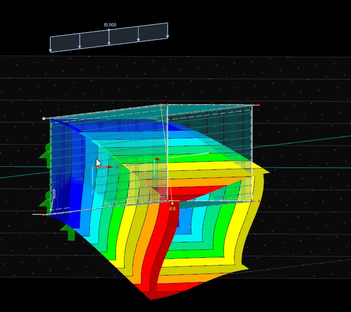
How can I understand possibility of using this sections in terms of torsion in a beam - which creates bending moments in a fillet weld. I want to asses safety of this solution.
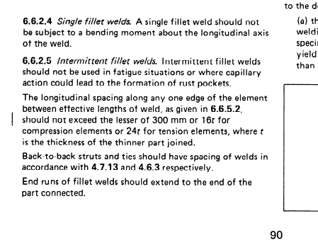
As per bs5950-1-1990-structural-steel-hot-rolled.pdf - single fillet weld should not be subjected to bending.
But I can see in that rectangular build-up hollow section is allowed to be used - webs are welded as single fillet weld.
How can I understand possibility of using this sections in terms of torsion in a beam - which creates bending moments in a fillet weld. I want to asses safety of this solution.