Eng-Tips is the largest engineering community on the Internet

Intelligent Work Forums for Engineering Professionals

Single lap joint simulation using Abaqus 2017

Status
Not open for further replies.

Emile Pantaleao

Student
Jul 25, 2023
11
0
0
IT
Hello,

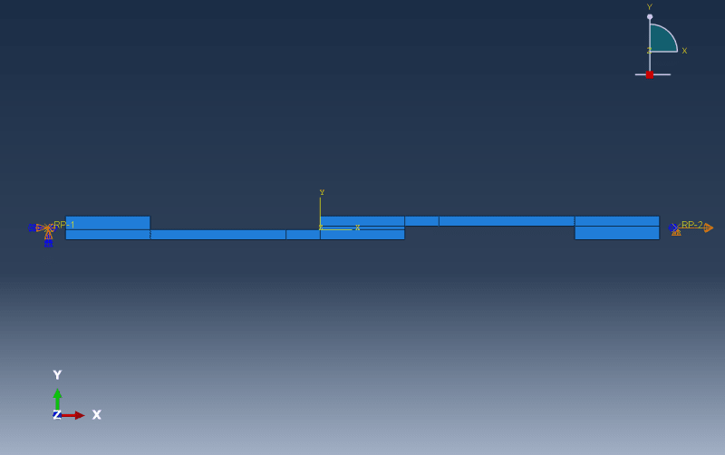
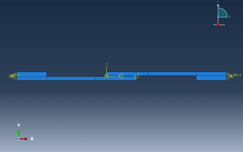
I am studying the stress repartition inside of the adhesive layer of a single lap joint (SLJ).
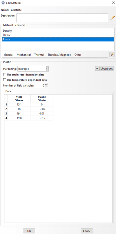
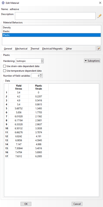
The substrates and the adhesive are considered elasto-plastic with a hardening plastic behavior obtained by SLJ shear tests and tensile tests.
The model 2D plane strain, the solver is Dynamic, Explicit.

My goal is to obtain the elastic and the plastic hardening behavior using an Abaqus model.

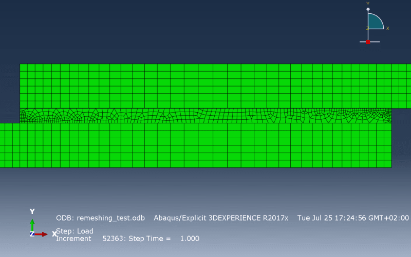
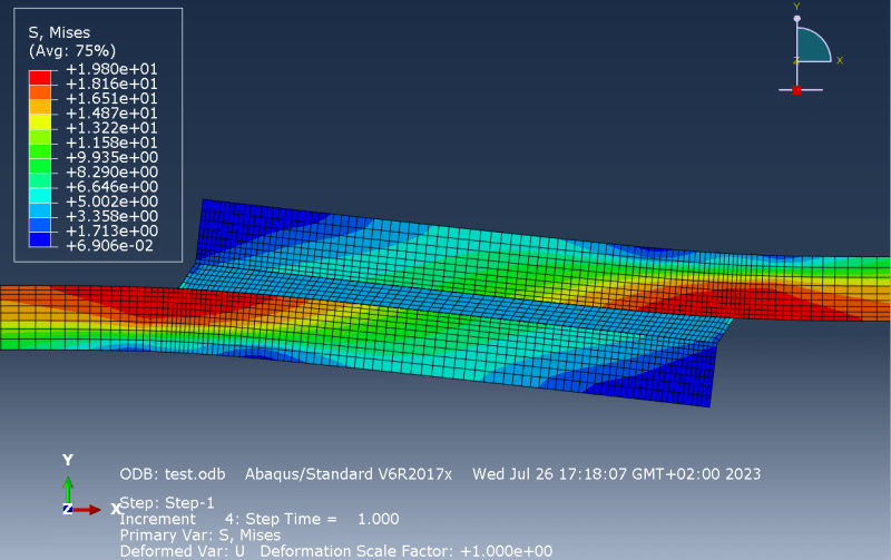
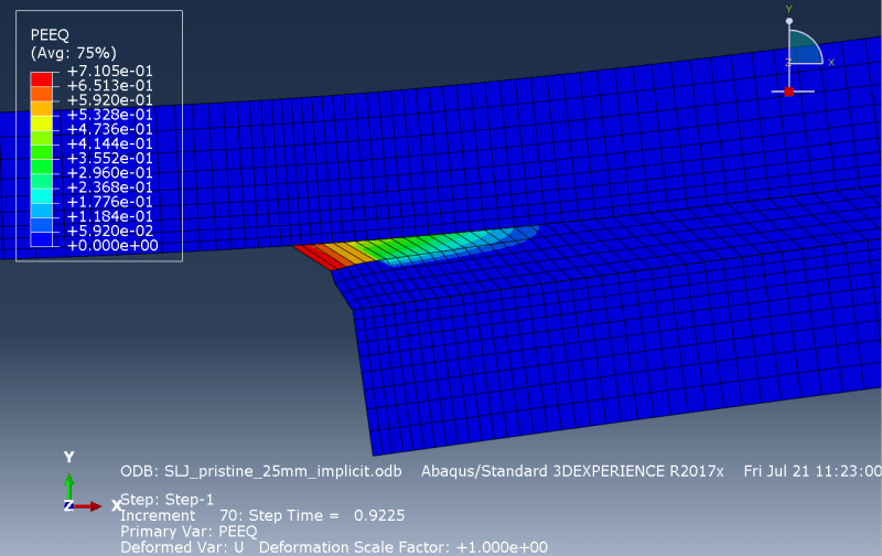
However the adhesive behaves incorrectly.

incorrect_stress_repartition2_nvjjgi.png


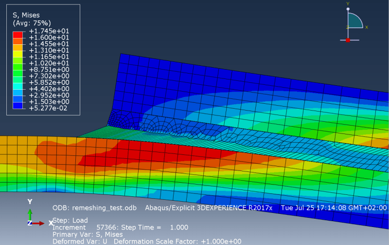
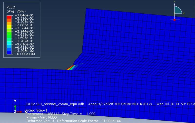
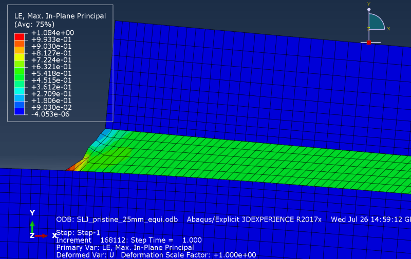
Here only the first row of elements of the mesh is deforming. The stress is expected to be higher in the corner of the adhesive and might be the reason for the high strain.
However, it should be shared with other elements.

This strain does not appear when the adhesive's behavior is only elastic.

So far I have tried the following methods to fix the problem without success:
- interface (substrate/adhesive) behavior : cohesive, no debonding,
- interface behavior : tie constraint,
- merging the nodes of the interface,
- refining the mesh,
- change from implicit to explicit solver,
- remeshing rules and adaptative mesh for the adhesive layer.

No matter how refined the mesh is, only the first row of elements is deformed.

This picture shows how the adhesive is expected to deform :

expected_behavior_rdomge.png

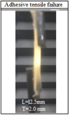
[Parametric study of hot-melt adhesive under accelerated ageing for automotive applications, E.G. Koricho et al.]

Thank you.
 
Replies continue below

Recommended for you

vM stress may not be the best stress to plot ... maybe shear stress (as that's what the adhesive is supposed to do).

what displacement are you plotting ? maybe the displacement in the other element is small (but not zero) ?

if you're modelling that picture, maybe your loading is not "correct" ? I see (in the pic) there is a loading fixture (at the bottom) with your specimen attached. Then the applied load should be offset from the specimen (mid-depth of the fixture), or possibly shear applied to the interface surface.

"Hoffen wir mal, dass alles gut geht !"
General Paulus, Nov 1942, outside Stalingrad after the launch of Operation Uranus.
 
The mesh in the adhesive is very strange. Please post an undeformed picture.

What are the exact adhesive and substrate properties that you are using?

How are you implementing "plane strain"?

 
rb1957,

The stress repartition is consistent as it is expected to concentrate in the bottom left and top right corners of the adhesive.
Indeed vM stress is not optimal and I should focus on shear and peel stress. But my main issue is the strange mesh deformation.

I am not sure of what you mean by the displacement I am plotting, every element undergoes displacement. But only the first layer of elements is deformed, and the others are barely deformed.

Concerning the loading, I used the following model :

loading_qne2q3.png


The adhesive (in the middle) is tied to 2 substrates.
The left one is coupled to a reference point with the BC "ENCASTRE", both displacement and rotation are constrained.
The right one is coupled to a reference point with a displacement BC of 3mm in the X axis and a BC preventing Y axis displacement.
The slave region of the coupling interactions for both substrates is the vertical surface closest to the concerned RP.

This loading scenario reproduces the experimental procedure and RPs were used to obtain Load/Displacement curves.

The load appears coherent, I think the problem resides in the mesh, the interface behavior or the materials properties.
 
SWComposites,

Here is a picture of the undeformed mesh.

remeshing_test_rnslzl.png


It was refined where the stress is concentrated.
I also tried a model with a regular square mesh, but the same behavior appears.

The elastic properties of the substrate are :
E = 2040 MPa
v = 0.4
Density : 5170 kg/m^3

Plastic properties :
substrate_wmucx5.png


The elastic properties of the adhesive are :
E = 10 MPa
v = 0.4
Density : 980 kg/m^3

Plastic properties :
adhesive_dpfb5o.png


The adhesive is very ductile and is expected to deform a lot.

About the plane strain, I am not sure of what you are refering to but the model was made in 2D.
In my previous post to rb1957, you can see how the load is applied.

I am sorry if my answers are inaccurate, I am inexperienced with Abaqus.
 
What if you use structured, uniformly refined mesh for the adhesive ? You could also try modeling the adhesive with cohesive elements, using a continuum-based constitutive model (a standard material model like the one you have instead of the traction-separation model typical for those elements).
 
"what displacement are you plotting ?" ... total displacement, dx ? dz ??

how are you constraining the different meshes ?

can you explain your end modelling ? Are the loading fixture at the different ends on the same side of the specimen ?

"Hoffen wir mal, dass alles gut geht !"
General Paulus, Nov 1942, outside Stalingrad after the launch of Operation Uranus.
 
FEA way,

Thank you for your advice, I realised that adhesive section was defined as "Solid" instead of "Cohesive".
Does this mistake have significant impact on the results ?
I will try changing section and element type in the mesh.
 
rb1957,

I plotted total displacement.

What do you mean about mesh constraints ?
If you talk about mesh controls and element type, the elements are default plane strain and the shape is quad (technique : free and advancing front algorithm).
No ALE Adaptative Mesh was employed to obtain these results.
You can see that the subtrates were partitioned for meshing purposes.

Here is how I coupled the reference points to the substrates :

interaction_xrhcon.png
 
I'm noticing that the adhesive nodes do not align with the substrate nodes ?

I don't think your end modelling is correct. I think the loading fixture should be constrained to the RBE, not the fixture and the specimen. But then I could be "wrong". Are the test fixtures really offset ? I think your original picture is showing more bending. One idea might be to model the adhesive as metal (so you've got one single piece. There should be a straight line between the 2 load points and the center of the specimen, as you've got, only I think the LH load point should eb higher and the RH lower (at the middle of the loading fixture).

I'm not sure "total deflection" is the right one, to highlight what you're trying to see.

"Hoffen wir mal, dass alles gut geht !"
General Paulus, Nov 1942, outside Stalingrad after the launch of Operation Uranus.
 
1) get rid of the cohesive elements and make the substrate and adhesive element meshes line up using the same nodes
2) run the model first with linear properties and plot the displacements

FEA_way - I can't remember, does Abaqus have plane strain elements that convert the material properties automatically? or does the user have to adjust the material properties to get a plane strain response using a normal shell element?
 
Oh, I see you might have tried the above already. Please post the deformed plots for linear elastic case.

It might be that the adhesive is too soft. 10 MPa is 1.4 ksi - for modulus that is very very low. I doubt it is correct. Also 2040 MPa is 0.3 Msi - which is very low for a substrate. What are the exact materials for both?

Also, 0.4 poissons ratio might be a problem with plane strain; try changing it to 0.3 for both materials.

Also, try changing to normal plane stress shell elements and see it that gives a better response.
 
rb1957,

Indeed for the presented model, the adhesive nodes and the substrate nodes do not align.
However I also conducted simulations with aligned nodes and I witnessed the same issue.

In the experimental study, the fixtures were added to each end of the substrates in order to avoid the misalignment. This prevented additional bending moments.
I followed the loading scenario specified in the experimental study so I am very confident it is coherent.

Thank you for you advice.
 
SWComposites,

Here is the deformed plot for linear elastic properties.

elastic_ixmayc.png


For the linear elastic case, the weird mesh deformation does not appear, so I believe my model behaves incorrectly with plastic deformation.
Nonetheless, I tried doing simple tensile tests for both materials in order to make sure that the plastic behavior described was correctly implemented. I obtained Load/Displacement curves very similar to the experimental tensile tests.

The adhesive is polyolefin and the substrate is polypropelene.
The original experimental work does not specify the plastic properties of the adhesive. The researcher told me it was polyolefin with a 10 MPa Young's Modulus.

I will try changing the Poisson's ratio for both materials, and the elements.

I did not precise the model dimensions, but the adhesive layer is 1mm thick and 25mm long, and the substrates are 3mm thick and 100mm long.

Thank you for your advice.
 
what I suspect, if you look at the linear model stresses, there is a peak stress at the corner element in the adhesive. when you run with nonlinear properties, that element first goes into the plastic region, and stress increases in the adjacent element in the same layer. the elements in the other adhesive layers never go into the plastic strain region. try plotting the total strain in the nonlinear model results.
 
I think the bending moments, if there in the real test, need to be modelled. Clever specimen deign can keep things straight in the test ...
use a clevis fixture at both ends, pad the specimen to align. The specimen will need time/distance to shear load out of the packer; or
test with back-to-back specimens.

But you'll no doubt say "the test has been run". So you need to carefully model the test set up.

"Hoffen wir mal, dass alles gut geht !"
General Paulus, Nov 1942, outside Stalingrad after the launch of Operation Uranus.
 
rb - the test setup as modelled is how most single lap shear tests are run. see ASTM D1002. the adherends at the joint rotate as shown in the plots above. not the best or most representative test setup, but that is what everyone runs.
 
SWComposites,

Indeed you are right, the plastic strain seems to concentrate in the element at the bottom left corner and only spreads in the first layer.

The following pictures show the equivalent plastic strain and the total strain respctively.

plastic_strain_yvdfgy.png


total_strain_fu00da.png


Is it possible to avoid such a behavior, and force the plastic strain to spread ?

Thank you.
 
In another model undergoing higher loads, this is what happens :

plastic_strain2_lkqpym.png


We can clearly see that the plastic behavior is wrong, but it behaved consistently for tensile simulations.
 
Status
Not open for further replies.
Back
Top