Emile Pantaleao
Student
Hello,
I am studying the stress repartition inside of the adhesive layer of a single lap joint (SLJ).
The substrates and the adhesive are considered elasto-plastic with a hardening plastic behavior obtained by SLJ shear tests and tensile tests.
The model 2D plane strain, the solver is Dynamic, Explicit.
My goal is to obtain the elastic and the plastic hardening behavior using an Abaqus model.
However the adhesive behaves incorrectly.

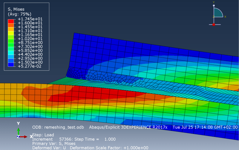
Here only the first row of elements of the mesh is deforming. The stress is expected to be higher in the corner of the adhesive and might be the reason for the high strain.
However, it should be shared with other elements.
This strain does not appear when the adhesive's behavior is only elastic.
So far I have tried the following methods to fix the problem without success:
- interface (substrate/adhesive) behavior : cohesive, no debonding,
- interface behavior : tie constraint,
- merging the nodes of the interface,
- refining the mesh,
- change from implicit to explicit solver,
- remeshing rules and adaptative mesh for the adhesive layer.
No matter how refined the mesh is, only the first row of elements is deformed.
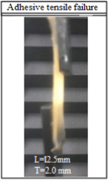
This picture shows how the adhesive is expected to deform :

[Parametric study of hot-melt adhesive under accelerated ageing for automotive applications, E.G. Koricho et al.]
Thank you.
I am studying the stress repartition inside of the adhesive layer of a single lap joint (SLJ).
The substrates and the adhesive are considered elasto-plastic with a hardening plastic behavior obtained by SLJ shear tests and tensile tests.
The model 2D plane strain, the solver is Dynamic, Explicit.
My goal is to obtain the elastic and the plastic hardening behavior using an Abaqus model.
However the adhesive behaves incorrectly.

Here only the first row of elements of the mesh is deforming. The stress is expected to be higher in the corner of the adhesive and might be the reason for the high strain.
However, it should be shared with other elements.
This strain does not appear when the adhesive's behavior is only elastic.
So far I have tried the following methods to fix the problem without success:
- interface (substrate/adhesive) behavior : cohesive, no debonding,
- interface behavior : tie constraint,
- merging the nodes of the interface,
- refining the mesh,
- change from implicit to explicit solver,
- remeshing rules and adaptative mesh for the adhesive layer.
No matter how refined the mesh is, only the first row of elements is deformed.
This picture shows how the adhesive is expected to deform :

[Parametric study of hot-melt adhesive under accelerated ageing for automotive applications, E.G. Koricho et al.]
Thank you.
