Continue to Site

Eng-Tips is the largest engineering community on the Internet

Intelligent Work Forums for Engineering Professionals

  • Congratulations SSS148 on being selected by the Eng-Tips community for having the most helpful posts in the forums last week. Way to Go!

Single Phase electric motor problem (No load high current and heating) 2

Status
Not open for further replies.

AR.

Electrical
Feb 28, 2021
14
Hi 
I have a single phase electric motor. I got it from a friend that did not use it for a while. I cleaned it up and it sounds that all components are ok. I removed all dusts and add some oils to the bearings. 
bearings are ok. I cleaned the connectors and checked them all and all sounds good. 
I did a beep test to find the connections between coils and wires. what I find is two separated coil, one with 2.5 Ohm resistance (blue - Yellow) and second one with 3.1 ohm (Black-Red).
I far as i understood, the 3.1 ohm coil is the starter coil as it goes to starter capacitor. the motor runs well and no noise comes out from motor. it turns well and the torque sounds good. 
Here is the problem:
the full load current is 6.4 A based on the motor characteristics label but when I run the Motor with No load, its current reach o 7.2 A !!!!
after 5 to 10 min operation, the motor case get hot. as it is class B motor, it can reach to 80 C.  But I think there might be something wrong as it took too much current under no load test and the generated heat sounds weird.

I though it might be due to centrifugal switch mechanism and electrodes that do not well operate.I tried to check if the centrifugal switch. I can hear that it operates and due to good start, it should be fine but I can not check if the start coil well disconnect or not (should be ok)   

some photos is attached to see the motor conditions. the schematic is based on what I tracked on wire management board and it sounds ok for me.

I did all I can based on my knowledge and experiences (Not too much) but I do not know what could be the problem.
any comments or idea is highly appreciated.
Waiting for your feedbacks

 
 https://files.engineering.com/getfile.aspx?folder=eac94b34-9f27-4ab1-bcaf-429f2aea2f46&file=Motor.png
Replies continue below

Recommended for you

You are confusing PU values with real values.
The real current drops considerably at low or no load.
The reactive current drops slightly at no or low load.
At full load, both real current and reactive currents are at maximum.
As the load decreases, the real current drops at a much greater rate than the reactive current.
As a result, the power factor drops, but the drop in power factor reflects a change in the ratio between the components of the current.
A low power factor causes a higher current to be drawn. This results in higher copper losses.
A misleading statement.
The power factor is a result, not a cause.
The power factor is a result of the ratio between real current and reactive current.
The power factor is what it is and by itself does not cause anything.

As the load on a motor is reduced, the apparent current is reduced.
As the load is reduced, the real current drops faster than the reactive current.
As a result, the PF drops.
Result, not cause.

The reason for the low power factor of a single phase motor is related to the low losses of an unloaded single phase motor.

Bill
--------------------
Ohm's law
Not just a good idea;
It's the LAW!
 
First, I really appreciate for all comments and even dArsonval comments even the way it was explained.
Well, As I tried to well understand most proposed ideas, I tried to add some loads on the motor and see the results.

The air gap between the router and magnets are rally small and less than 1 mm. I contacted the seller and he confirmed that he never did any machining on the motor and the reason he sold the motor was that he never used it.

there was a label on the motor case saying, it is a utility motor (somehow a general used motor) so it was not designed for a very specific application.
That's why I wanted to use it for custom table belt-disk sander machine. this weekend I added some loads (they I decided to use it - a V-Belt and my sander mechanism) the current drop to 6.9 A.
still way from the FLA but it drops a bit. I thought that the load is not high enough , so I tried to add more load manually, results was another 100 mA drop.
getting clos to FLA but it gets hot quicker than before (which sounds normal - More load more heat).
But at any cases, what I do not understand is why the NLA, is higher that the FLA. the motor is designed and rated for 6.4 FLA and normally it should not exceed its FLA.

dArsonval, I tried to verify the coils and they are really not dirty, they was some black spots on coils and I found that those are color. the case was sprayed with black color.

hope this help
 
> But at any cases, what I do not understand is why the NLA, is higher that the FLA. the motor is designed and rated for 6.4 FLA and normally it should not exceed its FLA.

When you say FLA, if you're comparing to labelplate, then you have a bunch of potential errors to consider (is nameplate wrong, is nameplate based on a different voltage as it was in your earlier data where you measured current when voltage was higher than nameplate, and is there an inaccuracy in your measurement).

> That's why I wanted to use it for custom table belt-disk sander machine. this weekend I added some loads (they I decided to use it - a V-Belt and my sander mechanism) the current drop to 6.9 A.
still way from the FLA but it drops a bit. I thought that the load is not high enough , so I tried to add more load manually, results was another 100 mA drop.
getting clos to FLA but it gets hot quicker than before (which sounds normal - More load more heat).
But at any cases, what I do not understand is why the NLA, is higher that the FLA

That's a stranger situation (current decreasing as load increases) and harder for me to understand. Voltage measurements at terminals might fill out part of the picture.

Here is a good EASA discussion of no-load current for THREE Phase motors. It doesn't show any mechanism for current to decrease as load increases.

Try analysing induction motor with equivalent circuit. Add a model of the power source as ideal voltage source with series R/L impedance before it gets to the motor (I know the actual power system could be a lot more complex but I think that captures relevant aspects for qualitative discussion). Make two assumptions: 1 - THREE PHASE MOTOR; 2 - LINEARITY. With these assumptions then the only thing that changes as you increase load is that s increases and R2/s decreases and since you are decreasing the impedance of one element within an R/L network than current must increase.

If indeed current is going the other direction (decreasing as load increases), then it would have to be explained by violating one of those two assumptions:
1 - non-linearities are playing an effect. As you increase load as Waross pointed out you may be decreasing terminal voltage and pushing magnetizing branch into saturation. Even if terminal voltage doesn't change, as similar load-dependent voltage drop appears across the stator leakage reactance (especially where it represents the endturns) and could have the same effect of pushing the magnetizing branch further into saturation.
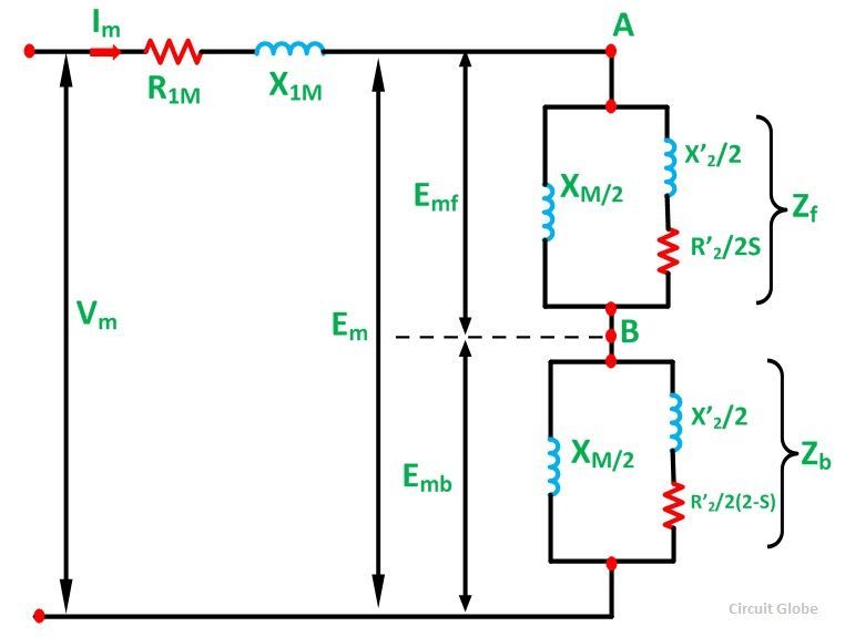
2 - Single phase motor might act way different than 3-phase motor. It's stator produces not only forward rotating field but also reverse rotating field. As I recall there is a modification of the equivalent circuit to account for this. I'd have to go back to my textbooks to refresh my memory on that one *

* EDIT Here is single phase induction motor equivalent circuit.
Let's say as you load the motor, s increases from 0.001 to 0.05. Then the effect on R/(2s) (which decreases by factor of 0.05/0.001= 50) is going to be much more pronounced than the effect on R2/[2*(2-s)] (which increases by a factor of 1.999/1.95 ~1.025) which might make us think current will increase with load. IF these two resistances were DIRECTLY in series THEN it's certainly obvious that the small fractional change in the smaller resistance (the reverse resistance) would be insignificant compared to the large fractional change in the larger forward resistance. But as a complicating factor, these two resistances are not directly in series, we have the series reactances X2/2 and the parallel reactances Xm/2 in parallel with each. Since R2/[2*(2-s)] << R2/(2s), the R2/[2*(2-s)] may tend to play a bigger role in determining the impedance of the reverse rotor circuit than the R2/(2s) plays in determine the impedance of the forward rotor circuit, which could possibly tilt the conclusion in the opposite direction (toward decreasing current as load increases). As an extreme example if X2~0 and we imagined that R2/[2*(2-s)] << |Xm/2| << R2/(2s) then the change in resistive component of the forward circuit would tend to be irrelevant and the change in resistive component of the reverse circuit would dominate (resulting in decreasing current as load increases). I don't think things are that extreme but I'll think about it some more (I'm open to comment).

1phasemotor_itvtnp.jpg


=====================================
(2B)+(2B)' ?
 
some data points for a few particular single phase motors. All of the following single phase motors show increasing current with load throughout the load range:
[ul]
[li]Baldor CL1410TM 5HP, 1725RPM, 1PH, 60HZ, 184TC, 3640LC, OPEN motor[/li]
[li]Baldor AFL3520A .75HP, 3450RPM, 1PH, 60HZ, 56Z, 3420L, TEAO motor[/li]
[li]Baldor CEL11301 0.33HP, 1740RPM, 1PH, 60HZ, 56C, 3418LC, OPEN motor[/li]
[li]Baldor CL3403 0.25HP TEFC HOR 56C motor[/li]
[li][/li]
[/ul]
I'm pretty sure all testing for these Baldor motors was done at rated voltage with no significant change in terminal voltage as load changed.

=====================================
(2B)+(2B)' ?
 
There are a couple of measurements missing.

What is the voltage at the panel?
How does the motor terminal voltage change as the motor current changes?

Bill
--------------------
Ohm's law
Not just a good idea;
It's the LAW!
 
AR.
Thanks for confirming my claim.
Just to add, in rare cases this happens also with some low-power three-phase motors (especially high pole motors) depending on their design.
 
I've been following this post for a while now and have no axes to grind.

I would point out to AR that FLA means Full Load Amps as far as I am aware, i.e. the amps, at 115V (not 123V) when the shaft output is 1/3 HP (250W). Nothing there about Amps at any other load and looking at this is it my simple mind here, but input energy is 736 W (115 x 6.4), but output is only 250W? I know there are things to do with Power factor etc, but this looks like s a really inefficient motor to me. Not too surprised it heats up - I assume the fan is working OK?

For things this small I would guess your variance on stated parameters is likely to be in the region of 10 to 15%.

So if it works, doesn't smoke or catch fire and you don't use it all day, then it looks Ok to me....

Remember - More details = better answers
Also: If you get a response it's polite to respond to it.
 
Motor characteristics would suggest it's not possible for the current to rise as load is removed. Without an explanation, I won't buy that the current can drop as the load is added. No actual explanation has been given yet.

The tests didn't prove anything unless full power measurements were taken. Of course (sadly), it's already been accepted as being absolute proof of a rather dodgey theory.

And all this for a hobbyist asking questions about a motor, a post I REALLY should have red flagged.
 
LittleInch - Input power of a motor isn't volts x amps. The motor power factor at rated load can have a big effect on that.
 
LionelHuz,
Just want to mention that it is not my hobby. I am an Electronic engineer, tend to change my field. I got involved in electric motors and if you had time to read all the tests that I have done you will find that it is for fun.
from the beginning, all I found was strange for me as I have never seen such results in electronic field. what is interesting is that will all experts here that trying to help me to well understand the situation and also gaining some experience (which a part of it comes from the one who works a lot with motors) still I could not find a complete and logic explanation for this issue.

that's true that I could not do all tests as requested as I do not have all the required equipment, but still I can learn from others (Waross and electricpete) since this might be the golden goal of having these sort of Forums.

I do apologize if it was time consuming for all and wasted your time. I will take the motor to a workshop to see if they can find something weird which explain the problem (or maybe no problem as some other experts said).
 
Check your voltage:
At the panel,
At the motor on open circuit.
At the motor at no load.
At the motor with some load.

As an example of voltage drop due to reactive current versus real current;
Assumptions for illustration:
Applied voltage at the panel = 125 Volts.
The magnetizing current is causing a 5 Volt drop in the feeder to the motor.
This is the voltage drop measured from the panel end to the motor end of the feeder.
This voltage drop is caused by a reactive current ans is 90 degrees out of phase with the applied voltage.
The voltage at the motor terminals will be √(125V2 minus 5V2) = 124.9 Volts.

An equal magnitude of real current will cause an in-phase voltage drop, and an in-phase voltage drop of 5 volts on a 125 Volt supply will result in a terminal voltage of 120 Volts.
This will drop the magnetic circuit below the saturation knee and drop the magnetizing current noticeably.

Note:
The series of voltage measurements that I asked for are comparative measurements.
We are more concerned with the changes in the voltages than in the actual voltages.
Even if your meter is inaccurate, the readings will provide information that may be valuable.

By the way, if the capacitor is connected in parallel instead of in series with the start winding, the results are unpredictable but that may cause excess current.
And;
Current dropping with load may be a sign that the voltage drop under load is lowering the saturation level and saturation based current.


Bill
--------------------
Ohm's law
Not just a good idea;
It's the LAW!
 
Status
Not open for further replies.

Part and Inventory Search

Sponsor