Continue to Site

Eng-Tips is the largest engineering community on the Internet

Intelligent Work Forums for Engineering Professionals

  • Congratulations MintJulep on being selected by the Eng-Tips community for having the most helpful posts in the forums last week. Way to Go!

Single-phase ground faults and phase to phase ground faults. 1

Status
Not open for further replies.

heberovchem

Electrical
Oct 14, 2008
10
I know that a single phase to ground fault causes a rise on the neutral potential, but I need to explain that (why). Is it because there has to be some impedance (even though it could be small) between the neutral and ground (through the return path)? If it is a return path shouldn't the neutral voltage be lower than the ground voltage (assuming to be zero at all times)? Now if that is the case how come the phase angles (phase to neutral vectors), in phase-phase to ground and single-phase to ground faults remain unchanged between the faulted phases or un-faulted phases with respect to neutral? I appreciate your feedback
 
Replies continue below

Recommended for you

You need to break everything down to their sequence components.

Positive sequence - normal operating rotation. It can ABC or ACB but it has to be whatever is standard. Positive sequence by definition is all three phases with equal magnitude and 120 degrees apart with standard rotation

Negative sequence - the exact same thing as positive sequence but opposite rotation. all phases are of equal magnitude and 120 degrees apart

Zero sequence - all three phasors are equal in magnitude and angle. This is sometimes called the residual since it is equal to I0 = (IA + IB + IC)/3

Ground faults, load imbalance, untransposed lines will all generate zero sequence voltage at the disturbance. Zero sequence voltage can also be looked at as the difference between neutral and ground. If there is a zero sequence path to a ground source, the voltage will generate zero sequence current.

Phase to phase faults don't generate zero sequence current. For a three phase fault, all the current going to the fault will be positive sequence current since the fault is balanced just like a very large load. For line to line faults, all the fault current that goes down one phase will return on the other faulted phase. There is no residual or zero sequence since the net current going to the fault is zero.

I am unsure as to what you are talking about in the last question. The voltage and current magnitudes and angles change during a fault. If you have a phase to phase fault, the voltages of the two faulted phases get pulled together. In a single line to ground fault, the voltages magnitudes and angles, with respect to ground change. How much they change depends on your grounding.

I think this clears up some if you review sequence components. Without sequence components, it is hard to understand unbalanced faults. All disturbances that are unbalanced produce negative and/or zero sequence voltage at the point of the disturbance, which decays as you move electrically away and deeper into the system.
 
Also, look up neutral point shift in ungrounded and impedance-grounded systems. There are plenty of sites that explain why it occurs.

xnuke
"Live and act within the limit of your knowledge and keep expanding it to the limit of your life." Ayn Rand, Atlas Shrugged.
Please see FAQ731-376 for tips on how to make the best use of Eng-Tips.
 
Thank you for your feedback, but here is what I meant when I asked the wordy question:

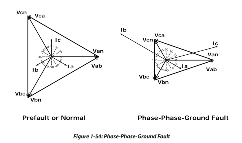
in a phase-phase to ground fault (bc fault Vbn and Vcn have same 120 angles, and their magnitude decreases):

image_ujxi1v.png


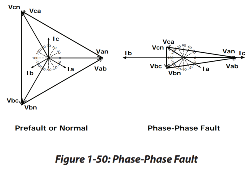
whereas (bc fault Vbn and Vcn have less than 120 angles and magnitude as before decreases),

image_saqarq.png


I am sorry I was not clear about my question, and I do have a basic understanding of symmetrical components, I just don't get those conclusions (especially how the angles decrease in one situation and the other stays the same).

Thank you for being so patient

:)
 
Phase to phase faults pull the involved phase voltages together.

Phases involved in a ground faults have their voltages pulled towards the ground point.

The phase to phase diagram has two of the voltage phases pulled together. This looks right to me.

I don't think I would think too hard about the phase to phase to ground diagram. There are a lot of system variables that could make it look different. I think that it might be right because for a phase to ground fault, the faulted phase voltage is reduced in magnitude but maintains the same angle. If you apply a ground fault to VB and another to VC, you get what they show if you assume that it will be similar to a single line to ground fault with the faulted phase voltage being less but of the same magnitude. So, I think it is correct for a solidly grounded system.
 
Thank you very much, with those three lines I think I got it now. I do not know why I was making it so difficult. Still, I followed your advice and reviewed symmetrical components again. Hopefully I will be able to explain to someone else if I am asked.
 
Status
Not open for further replies.

Part and Inventory Search

Sponsor