Eng-Tips is the largest engineering community on the Internet

Intelligent Work Forums for Engineering Professionals

Single shear bolt shear and moment diagrams

Status
Not open for further replies.

hootrpootr

Aerospace
Feb 28, 2020
27
0
0
US
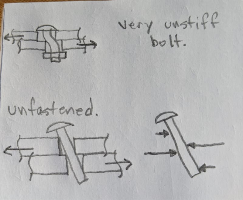
Hello, I’m trying to determine what the shear and moment diagrams of a bolt in single shear look like. Before anyone says it, I know that it’s rare that a bolt will ever fail first in bending, and this is something that typically isn’t even checked for.

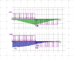
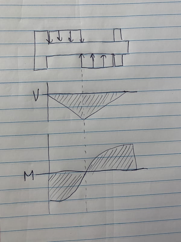
Anyway, I’ve assumed that the bolt is essentially a beam cantilevered at one end and guided at the other (guided end only allows vertical translation, no rotation). I’ve applied a distributed load acting downward over half the bolt length, and a distributed load acting upward over the other half. I found a website that uses these assumptions as well, and even provides a shear diagram (I’ve arrived at the same conclusion). Does the moment diagram match the drawing I’ve attached?

Website (see figure 4.2.4):
58CEBDA5-5DAD-4D9D-8B11-3D9C563C8A77_ptrtak.jpg


Thanks!
 
Replies continue below

Recommended for you

Generally that moment diagram looks pretty close based on your applied loads and restraints.

I'm not totally sure your applied load assumptions are accurate. That's going to depend a lot on what you're fastening, bolt pretension, and other stuff. I can expand on that if you'd like me to.
 
Thanks for both of the responses. After looking through TR-12 I was able to find some figures that resemble my drawings (slight differences because of different assumptions, etc).

WeezerMike, if it’s not too much to ask, I’d appreciate hearing your thoughts in more detail. I know that I did make some simplifications/assumptions when determining my applied loads. I simply came to the conclusion that the two plates would bear on the bolt in opposing directions (again assumed uniform pressure), hence the two distributed loads. I didn’t take into consideration any preload at this point.
 
uniformly distributed shear is an assumption, maximising bolt bending. As the joint becomes critical, shear load peaks at the shear plane, so a triangular assumption is often used.

Spacers are often a problem, dead space between the two shears increases bolt bending.

Preload would affect this much (it affects bolt strength). Preload affects the %age of shear transmitted by the plates being compressed together, usually neglected in analysis but exists in the real world.

another day in paradise, or is paradise one day closer ?
 
So, rb1957 already touched on this a bit.

To have uniform force, you need the deformed shape of the bolt to match the shape of the side-walls of the hole so that there's flush and uniform bearing throughout, and you need enough pretension in the bolt to prevent any rotation. So essentially, the assumption that there's a uniform force on the bolt seems appropriate if the stiffness of the bolt in bending and the stiffness of the head/nut to prevent rotation are both very stiff. That's probably a safe assumption if your bolt diameter is at least as big as the thickness of the fastened plates.

If your bolt is somewhat flexible, uniform loading could still be appropriate if the forces are high enough to deform the sidewall of the bolt hole so that it matches the deformed shape of the bolt.

Now, if you have a very flexible bolt in bending without high enough loads to deform the bolt hole, then the bent shape of the bolt won't match the shape of the plate material inside the hole. As rb1957 said, your stresses will creep closer to the flaying surface. Hopefully my crude sketch below illustrates this.

You can also have so much rotation of the bolt, that you get complete force reversal within the thickness of each fastened part. If you imagine a bolt without a nut that acts only as a dowel you will still get a lot of shear capacity, but for stability the bolt needs to rotate until it's pressing on both sides of the hole in each plate. ...also crudely sketched below.

Now, that's all for standard steel-to-steel connections. There are plenty of other things to consider like whether your holes are oversized, whether tightening your bolt creates enough clamping force to carry the entire shear force in friction between the plates, whether the holes in your plates are punched or drilled (punched holes often increase in diameter slightly as the punch goes through the plate), etc.

There are a lot of potential bolt behaviors depending on the materials and configuration. The diagrams from the NDS for bolts in wood might illustrate that variety.

IMG_20200714_090802_mulzfl.jpg

download_vgyogc.jpg
 
The moment diagram is incorrect, if the right hand support is free to rotate, and slide up and down (guide). Both shear and moment diagrams are incorrect, if rotate the guide 90°.

image_guc9jv.png
 
"if the right hand support is free to rotate" … but it isn't …

from OP …
"the bolt is essentially a beam cantilevered at one end and guided at the other (guided end only allows vertical translation, no rotation)."

another day in paradise, or is paradise one day closer ?
 
rb,

Thanks, I missed the "no rotation" for rotation free. Then the diagrams are correct without other complications.
 
Status
Not open for further replies.
Back
Top