Continue to Site

Eng-Tips is the largest engineering community on the Internet

Intelligent Work Forums for Engineering Professionals

  • Congratulations KootK on being selected by the Eng-Tips community for having the most helpful posts in the forums last week. Way to Go!

Single shear joint fastener flexibility comparison to FEM

Status
Not open for further replies.

BragiBaldursson

New member
May 5, 2021
30
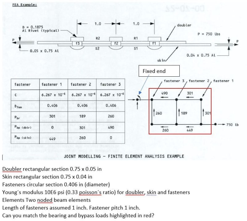
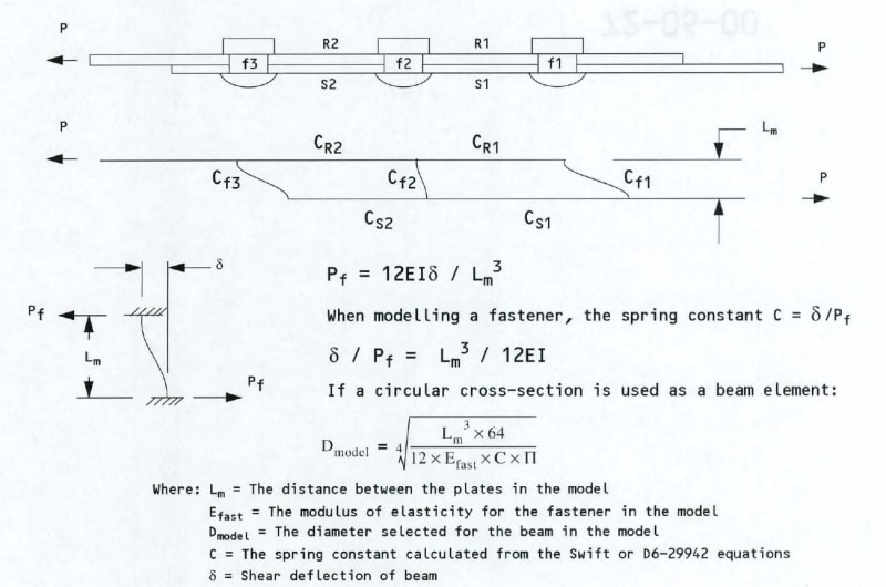
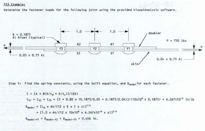
Can an FEA expert with access to Abaqus/Nastran see if they can match this simple problem of a single shear joint with riveted fasteners. Fasteners are to be modeled as beam elements (circular) tied to the doubler and skin (1 inch apart). Fastener diameter is calculated from Tom Swift´s fastener flexibility to be 0.406 inches in diameter and fastener length of 1 inch. I would like to know if the hand calculations compare well with FEM results for the bearing and bypass loads.
b1_pmwyuo.jpg

b2_iymyvv.jpg

Capture_hmyrt9.jpg

problem_w2ewii.jpg
 
Replies continue below

Recommended for you

a) why can't you make a FE model yourself to compare to this analysis?
b) is this a homework problem?
c) the rivet length is no where near 1.0 inch; why would that be used in a model??
d) and why would the fastener be modelled with dia = 0.406, when the actual diameter is 0.19 inch??
e) have you tried using the fastener distribution s/w here:
 
Hi SWComposites.

a) why can't you make a FE model yourself to compare to this analysis? I do not have access to FEM.
b) is this a homework problem? [highlight #A40000]No for work.[/highlight]
c) the rivet length is no where near 1.0 inch; why would that be used in a model?? As explained above this is a methodology suggested by Boeing to calculate bearing and bypass loads with FEM. You assume fastener length is equal to 1 inch and calculate what diameter fastener gives a value of fastener flexbility calculated previously per Swift.
d) and why would the fastener be modelled with dia = 0.406, when the actual diameter is 0.19 inch?? Explained in c above.
e) have you tried using the fastener distribution s/w here: I have not but have my own excel tool to do that. I want to see how FEM compares.

Bragi
 
You've said this is a problem for your work. So you're asking people to freely perform an analytical verification for you? That's not really the purpose of this forum.

Also, in the future, please refrain from cross posting in multiple forums.

This is a topic that has been studied at length in the industry. If you have no access to FEM and aren't willing to get it, then I suggest you look for existing publications and reference papers which have compared 1D stiffness-displacement based Load Transfer to FEM.

Since these models assume a truly 1D scenario, the results are never going to be an exact match. The LT is also going to be influenced by your choice of fastener flexibility equation.

In my experience I've found Swift's equation to predict the highest peak LT compared to other equations (it is the stiffest fastener model).

Keep em' Flying
//Fight Corrosion!
 
LiftDivergence thank you for your warm and positive response. I work in a small company that does not have the resources that others have. I have in my past time been very interested in this subject and have read a lot of papers, thesis and standards on the subject. I found this Boeing course I took a long time ago and started working through it and was intrigued to see how their FEM suggestion would compare.

I m sorry if I stepped on your precious toes and i hope they did not fracture.
 
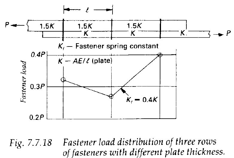
On a cursory check I found in my stash the following documents which include a comparison of FEM results for individual fastener loads to hand calculations:

I'm sure you could find more with some searching.

However, in the end, the method written by Swift which you reference above is a form of the matrix-force method of analysis. This was very common when analysis semi-monocoque flight structures started t0 become much more sophisticated. Argyris has written extensively about it's application to airframe structural analysis.

Matrix method is essentially a precursor to FEA. FEA in no way obviates hand analysis, if the model is small enough (which in this case, it definitely is). You may recall from study that FEA basically works by assembling a global stiffness matrix and relating it to a displacement matrix. You may find a solution using a number of matrix algebraic steps. For example, in college, I was taught Galerkin's method. The reason complex FEM software packages exist is that generally the size of the model we want to deal with is too cumbersome to solve by hand.

What I'm saying is that you don't need to have extensive resources to do simple FEA. You could probably make a script to perform 2D FEA to check your answer pretty neatly. Fortran would work, or possibly even VBA.


Keep em' Flying
//Fight Corrosion!
 
Thank you LiftDivergence.
I have read the second thesis. Problem with theses is they very often leave out pertinent details as they are often sponsored by corporate. Like these sponsored by Saab Aircraft.

The example i posted above is the only one where I have found step by step instructions on how to model the joint and that is why I was curious how it compares.

All the answers I get is people offering up different type of hand calculations or estimations from graphs. Makes you really wonder how good and reliable the FEM models industry is using.

Bragi
 
If you're familiar with hand coding Nastran decks, try building a model in Mystran.
Also take a look at the Huth formulation for fastener flexibility.
 
Here we are years end with experts that are eager to comment and indicate they have all the answers but nobody offering concrete advice for a simple problem that is used widely in all structural analysis. Where are we as a world if we cannot share how exactly we do things in our work. Sorry for my frustration but I have so much had it with engineering kinga that think they know it all but are afraid to share their knowledge.
 
For a simple model I'd try:

Straps = rod elements, collinear.
Fasteners = Cbushes at the coincident nodes using huth formulation for shear stiffness.

The really contentious part of these types of problems is the assumed formulation for the fastener stiffness. As for the calculation method, whether you use fem or a hand calc matrix solution the results should be very similar. Some further consideration is required if it's an unusual joint, eg thick stack up, multiple straps, composites, varying fasteners.

Happy new year, good luck...
 
Hi Bragi,
I hear your frustration but this may come from a mismatch in expectations.
Since you have already excerpted a bunch of figures from good textbooks like Niu and say you have Schijve's, I am at a loss as to what you are missing. I'm glad to see you here posing interesting questions, but at some point I don't hold your hand any more and you're able to take it on your own. If you also have the Boeing course notes then shouldn't every step of the method be right there before you?

At various times your posts have appeared to ask questions at the student level, rather than as a practicing engineer. Perhaps that's a mistaken impression but on the slight chance that you are in fact a student, please make sure you are taking full advantage of the educators and training materials available to you at your institution, all of which should be able to help you.
 
why do you use rod elements that can only carry axial loads and torsion and not bar elements that have bending?
The Huth fastener flexibility gives values with units of m/N. Do you just use the inverse of this for the PBUSH K stiffness value?
What length do you use for the CBUSH element?
 
Regarding element type:
For fatigue analysis of a fairly conventional lap joint (using the proprietary methods that I'm used to) the effect of moments due to loadpath eccentricity are addressed separately, not in the loads model. By that method you can use a 1d model such as the one I've described to calculate joint load distribution (bearing and bypass loads).
In short, yes, you need to account for loadpath eccentricity somewhere in the analysis.

Yes, stiffness is the inverse of flexibility.

Cbush length is Zero: nodes are coincident, it's a 1d model. Though see my note about accounting for eccentricity somewhere in the analysis.
 
Ng2020. If you have more complex joints such as doubler and tripler do you still use a 1D model for that as well?
 
I'm a few years out of practice, but you could well make quite a complex 1d model, as long as you're confident you are accounting for eccentricity elsewhere in the analysis. For example you might use SN data that's based on a joint of similar or equivalent configuration.
I'd try to get a good handle on the simple example you mentioned before pushing the capabilities of the method.
 
I got it to work using the beam methodology above with a fastener length of 1 inch. I had to use Y-symmetry on all nodes to guide the whole structure along the X axis. Great to know that this works as it is a very simple approach. Does not include secondary bending but gives me bypass and bearing loads.
 
TLDR ...

this is a "simple" compliance model, equating the deflections along different paths, like the displacement in the skin over the first pitch + the displacement of the 2nd rivet = the displacement of the doubler over the first pitch + the displacement of the first rivet. The first rivet has load P1, the second P2; the load in the doubler is P1, the load in the skin is P-P1. Then similar for second fastener pitch ... now load is doubler is P1+P2, load in 3rd rivet is P3, load in skin is P-P1-P2. Repeat to CL. A bunch of simulaaneous equations, solve for P1, P2, etc. Niu has all this in his book.

another day in paradise, or is paradise one day closer ?
 
read last post ... shouldn't need to assume a fastener length (beyond Tsk + Tdblr)

another day in paradise, or is paradise one day closer ?
 
Status
Not open for further replies.

Part and Inventory Search

Sponsor