Eng-Tips is the largest engineering community on the Internet

Intelligent Work Forums for Engineering Professionals

  • Congratulations waross on being selected by the Eng-Tips community for having the most helpful posts in the forums last week. Way to Go!

Single Storey Extension - 1900's - 1920's home.

Status
Not open for further replies.

liam1369

Structural
Nov 13, 2014
73
GB
Good Morning Everyone,

I am asking for some advice for a project I am about to embark on for a friend who is trying to extend his existing home at ground floor level only. The extension will occur at an existing profiled windowed wall and the existing cavity wall at ground floor will be removed to allow for the extension.

However, owing to the profile of the wall, as well as it potentially being load bearing with the joists (see attached) I am initially thinking he will need some steelwork transfer beams with plates above to pick up this perimeter cavity wall. This creates an awkward steel beam arrangements with angled connections.

Has anyone had similar difficulties with a project like this? Or can provide better advice in terms of methods to allow for this extension? I have attached a pdf which includes some annotated photos and plans.

The new extension will also require new concrete foundations, however, I believe owing to this house being constructed in the 1900's to 1920's, I believe it still may have brick foundations, can anyone comment on any potential underpinning issues or considerations that are typical for extensions.

Any advice is hugely appreciated and if you have any questions or clarifications I am keen to inform.

Regards,

Liam
 
 https://files.engineering.com/getfile.aspx?folder=c9154cb2-a9c3-4610-9f07-678ed14b0c9f&file=HOME_IMPROVEMENTS_-_TRANSFER_STRUCTURE_FOR_EXTENSION_1.pdf
Replies continue below

Recommended for you

This is probably one of those projects where you need to:
A) Be prepared for backup solutions before starting
B) Do some site measurements and calculation estimates before starting

I would most be concerned with the foundations and tracking that load down.
I would also be concerned about supporting all that brick without damage during construction (usually contractors responsibility)
Other beam solutions to consider: engineered wood? Steel for residential just seems like it would torpedo a project. But client's budget is their own.
I haven't (and won't) run numbers for your situation.
 
Your plan seems workable. Definitely support the brick on steel. Due to the shape of the bump out, you will need two cross beams and 4 columns each on new foundations elements.
 
Thanks for the responses. 8th street, as that wall is non load bearing and will only be transferring the load of the wall itself mostly, I’m hoping some padstones on the new wall and load spread down to new foundations will cover it. I might need a couple of columns for the ones behind.

That plan makes it very complicated, however, I think you are right, I think still is the only way. The cross beams will be quite complex to be fabricated and installed as well.

I wonder if there is a more efficient solution.
 
Do you have any comments on the cross beams required for the outline of the wall above? I have a feeling this will be complicated to construct and be quite costly with connections etc
 
Can't you put a transfer slab (rectangular) and support the slab with corner columns instead of this steel structure? That could also be your floor, no need for joists. I imagine it would be cheaper than the steel solution.
 
Designing the Frame: The configuration you’ve designed isn’t that uneconomical. I am a fabricator so I might just like have fun building it! But as an alternative you would consider putting a multi-ply LVL header in place of your steel beam across the opening (before the jet out), and affix joists via hangers that are supported on another LVL in place of your other beam (note: exterior beam is dropped so joists are resting on top of it). I’ve drawn a quick sketch in CAD that I have attached to give you the jist. I’m not sure it’s cheaper per se but since it’s something within a general builder’s wheelhouse, quotes will probably be more reasonable. Note: you'll have to do a legit check of joist capacity / S.L.S because while it is a short span, they will be absolutely critical especially for deflection (though only on the wings). If you can't make it work with wood joists there's no reason you cant switch to steel joists that connect to the lvls in a similar fashion.

The benefit of this method is that you can slot the joists in the wall prior to demo and that combined with the helifix ties (see below) you’ll be golden.

Construction Concerns: As others have mentioned, you will want to take care with the existing masonry during demo. You’ll likely need a temp shelf if you don’t go with the above method of slotting joists prior to demo and I would without question use helical retrofit ties (see here:
Footing Considerations: There is nothing particularly special about this project / anything critical to keep in find. Perhaps a few notes: You’ll want to take care not to disturb the existing foundation by hand digging at the building face. Hopefully the existing footing is below your local frost line (should there even be a footing. Sometimes these old beauties have just a wall thickening). In which case, all you’ll do is mate to it and build up. Going below isn’t a problem but don’t stop short of the existing depth.

EDIT - Link doesn't seem to be attaching to this post so here is the direct:
EDIT 2 - In case it's not clear when you originally slide the joists into the cavity you keep them long so you can support them beyond the new LVL location. This is to facilitate demo of the wall / erection of new lvl. The critical load on the joists is actually during construction, not service, because of the increased span during this time.
 
Hi Enable,

Thanks very much for the detailed response, very helpful and insightful.

Yes I understand that the deflection might be governing the design, owing to supporting the masonry above. Therefore, I would want to limit it to L/360.

In terms of foundations, as this is in London, I am likely going to specify a minimum 900mm / 1000mm deep foundation. I can imagine it will be below what is existing, I forsee the existing foundations being as you mention a strip or a stepped brick foundation. Therefore I will need to go lower, therefore, it will need some shoring temporarily.

Thanks very much for the links and information. Do you perhaps have a link to your fabrication company? Do you offer installation services as well? Perhaps you can private message (pm) me?

Regards,

Liam

 
Thanks for the sketch too. I was planning on not relying on posts where possible (I need to look into this a bit more). I was going to bear onto the wall with appropriate padstones and then spread down to hopefully optimise foundations and not require a pad. Not sure if you have seen this down before with the Multi-ply beams.
 
Assuming that you will be framing the extension conventionally (2x6 at 16” c/c or something similar) I agree that you would place the LVL on top of the frame with a double top plate. I would also connect it via hurricane straps to help provide some lateral stability to the member while it is still untied/blocked by adjacent rafters. The posts were quick just to indicate loads go down here (and if it were me I would just quadruple up a stud underneath the LVL)

I’m not sure what you mean by padstones? Isn’t the new wall going down to a CMU or concrete foundation wall that’ll extend 6” above grade? A 8” thick solid CMU wall will provide sufficient bearing I would suspect.

Foundation: Like you said if you need to go lower just lag it with wood on a temporary basis. You’ll be disturbing less than a 3’ wide section and so even if the soil entirely fell out, you’d be fine. Well…the house would be fine that corner of old brick may start to do something funky. Anyways, if any soil comes out during this process you can fill the void with cement prior to pouring / blocking the foundation. Often I’ll use the temp lagging sheet as a form and pour flowable non-shrink grout into the void.

I know of two Londons. One close and one on a different continent. I suspect by the nature of the house it’s the latter. Rather expensive to ship steel across the ocean to an Island! The LVL solution is probably cheaper lol

Another important thing to consider: detailing for water above the new extension will be tricky. That existing masonry will have no weep holes at the cut line and at some elevation above the new roof line you will want to build a shelf wrapped in blueskin to make sure the water does not track into the building. I would not rely purely on exterior face installed flashing like most builders would suggest (asking for serious trouble). This would usually be an architect's problem but since you are QBing this for a friend, I suspect it'll fall on to you.

As an aside, the plan I proposed more or less assumes you have the head clearance for two dropped LVLs (the interior one dropped below the existing joists and the exterior one dropped below the new joists). Seems like you might with ample room above the window and a few steps to the main floor from the exterior. That is surely the most economical way. BUT if head clearance is an issue (around these parts you’ll want 6’-6” minimum) you can do the same thing but the interior LVL will need to be placed at the elevation existing joists, which isn’t a problem it just means the existing joists need to be cut to slide the new joists in. You’ll support the existing joists one at a time either side of the cut, slide in the new joist, support the old off the new w/hangers, and proceed to the next one.
 
Hi Enable,

It is London UK :).

I'm thinking it will need to be steels picking up the existing walls as they do support a portion of a hip roof.

As the walls are being extended out I am aiming to sit these new steel beams on the walls but we will need padstones / concrete blocks to rest them on first, before the load is distributed down the wall into the foundation. CMU construction is not used commonly here in the UK, it will most likely be blockwork cavity walls.

Many thanks for your help again.

Kind regards,

Liam
 
I would probably go with a similar configuration, even if using steel, because it allows you to use the new structure as your temp support for the wall. I've drawn a few more sketches including details of the finished assembly and how it integrates with your water management system. Details will change depending on assumed elevation of your new roof but this is probably close to how I would do it.

Elevation View:
Details:
Plan View:
Good luck!
 
Hi Enable,

You efforts are hugely appreciated. Many thanks.

Liam.
 
Hi Enable,

I am still concerned with not putting a steel beam directly underneath the wall. Otherwise the wall will be sitting directly on a floor plate before this load being transferred to the beams.

I believe a more suitable solution will be to put beams at an angle directly under these walls? I can then put additional beams in to provide lateral restraint.

I am a bit concerned with the floor plate and overall details associated with landing the wall on a floor plate.

Liam
 
 https://files.engineering.com/getfile.aspx?folder=44f00389-d588-4fe0-b0f9-6b4f3a5c15d4&file=Document_13.pdf
The problem with that solution is constructability. Maybe there is some way that I have not envisioned but if you don't have perpendicular cross beams how does one erect the frame you've drawn in place while maintaining integrity of brick above? Lintels won't help because you need to take out the entire face and will have nothing to span to. The cross beams were spaced such that the brick was never spanning more than a foot and a half or so, which is perfectly adequate.

I don't disagree that direct beneath is preferred from a structural point of view but very hard to erect in practice without things going wrong. Also, what's the geometry of the connections? Hard for me to tell but if the angle is more acute than 30 degrees you'll have a problem with not having a qualified weld procedure for your shear tabs or whatever connection you design between main beams and angled beams.

....okay maybe thinking about this a bit. Lets say the connection detail isn't an issue. You can make a custom fabricated lintel, YES! We can do this. Okay, so your temp lintel will be one that has its long length in line with the angled walls. But on either end of that lintel, instead of just cutting flush, you will weld 150mm perpendicular angles that'll be on the same plane as the two intersecting walls (the one at the main house face, and the other at the jet out). It'll look like a Z but on a skew. More like ----\___

For an erection procedure you could do: Retrofit tie as before. Erect the interior beam. Place the custom amazing lintel we just made at some distance above the top of new cross beam. Erect a temp beam beyond the jet out wall line for the cross beams (which you will keep long) to sit on. Then remove brick and slide in the cross beam. Connect cross beam to interior beam however you decide to do that. Do same for other side. Slide in a few perpendicular beams to longitudinal beam at some level above (support either side) to keep brick above from cracking. Remove the lower wall. Erect permanent jet out beam. Cut long cross beam ends.

Can be done. Only problem is you'll need a decent builder.

 
First off, go see if anyone else down the street has extended out the back and see what they've done....

At 1900 to 1920 you should allow for needing to underpin the existing foundations where the beam will sit. They might have stood for 100 years, but modern building regs need 1m down. You won't find out until you do some serious digging so allow for them and then if you don't need it it's a price reduction.

Then why not just take the entire wall down including the first floor and square it off? This would allow you to open up the entire width of the downstairs kitchen and simplify the beam. Maybe even a balcony? or Juliet balcony?

You've go a bit of work to do on the roof to accommodate that, but this a lot easier than supporting all that brickwork and the fancy support structure. But looking at the other houses is the bay window roof a flat roof?

Remember - More details = better answers
Also: If you get a response it's polite to respond to it.
 
Hi Enable,

Thanks very insightful, will look into this again.
 
Littleinch,

That may be a possibility, however, that is not an option yet. The wall is supporting a partial hip roof so will have rafters coming onto it as well so will complicate the roof a bit.

In terms of underpinning, yes will need to underpin where required.

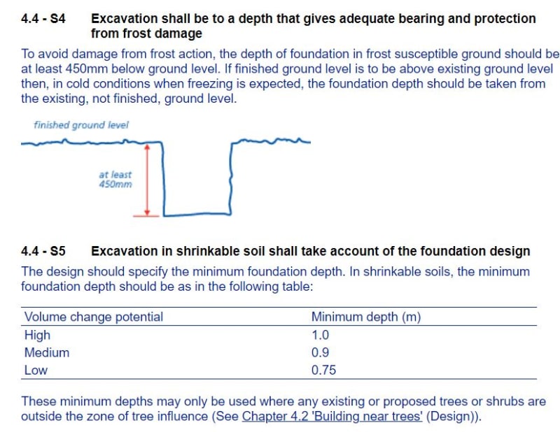
What do you mean 1m down? Do you mean the depth of the actual concrete? Usually it is 450mm deep / below the ground for frost and then yes 900mm-1000mm thick concrete to support the loadings. However, yes will underpin where required / if required.
 
Depending on the ground min 1m below ground.

Most footings of that time are 18 inches.

Remember - More details = better answers
Also: If you get a response it's polite to respond to it.
 
LittleInch,

I think we are discussing the same thing?

NHBC guidelines recommends a minimum of 450mm cover of the ground before the start of the foundation for frost protection. The foundation itself with then be circa 750-1000mm typically, therefore, in London I usually specify 1000mm.

See sketch for clarity. I would never simply recommend 1000mm below finished ground in general, as it would make the excavation very deep and also does not tie in with brick and block coursing.

Liam
NHBC_Guidelines_fzfqlj.jpg
 
Status
Not open for further replies.

Part and Inventory Search

Sponsor

Back
Top