Deener
Mechanical
- Aug 30, 2018
- 49
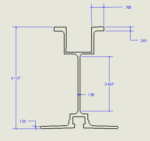
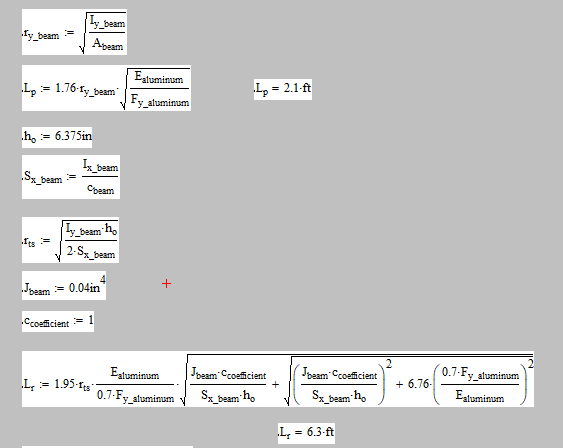
I'm evaluating the flexural capacity of a simply supported 6 1/2" deep Aluma beam with a point load (dead = 170 lbf, Live = 1000 lbf) at mid span (span is 10ft). Assume the beam is braced at end points only. Below is a snapshot of the aluminum beam cross section. Using the dimensions below along with AISC table B4.1b - case 10, and B4.1b Case 15, I can conclude that the top compression flange and web are compact(0.788in/0.260in and 3.469in/0.138in). . Table user note F1.1 in AISC 15th edition (pg 16.1-45) clearly states that the limit states to be checked for this case are yielding and lateral torsional buckling. Since my unbraced length exceeds the limit for inelastic lateral-torsional buckling, I have to use equation F4-3 which includes the critical stress. Now for my questions.
1. There is no documentation for the torsional constant of this beam. I have used a preliminary value for a W-shape (W6x8.5). Is there a way I can calculate this value myself? I'm using SolidWorks for CAD and it doesn't appear to give me this value as a section property.
2. The beam will be simply bearing on the bottom flange at either end. How can I confirm the bottom flanges are stiff enough to restrain this beam against rotation at the points of support as per AISC requirement F1.(b)?
3. If I limit the span of the beam to 6ft, the unbraced length is then between L_p and L_r and the limiting moment becomes dependent upon the plastic section modulus (as well as other variables in equation (F2-2). How can I calculate this value for the custom cross section? I know the ratio between S and Z for W shapes is 1.5. Could I apply that here as well?


Thanks in advance
1. There is no documentation for the torsional constant of this beam. I have used a preliminary value for a W-shape (W6x8.5). Is there a way I can calculate this value myself? I'm using SolidWorks for CAD and it doesn't appear to give me this value as a section property.
2. The beam will be simply bearing on the bottom flange at either end. How can I confirm the bottom flanges are stiff enough to restrain this beam against rotation at the points of support as per AISC requirement F1.(b)?
3. If I limit the span of the beam to 6ft, the unbraced length is then between L_p and L_r and the limiting moment becomes dependent upon the plastic section modulus (as well as other variables in equation (F2-2). How can I calculate this value for the custom cross section? I know the ratio between S and Z for W shapes is 1.5. Could I apply that here as well?


Thanks in advance


