Andrew Brockbank
Mechanical
Hi All,
I am currently designing a drone frame, and performing FEA on a quarter model (see below).
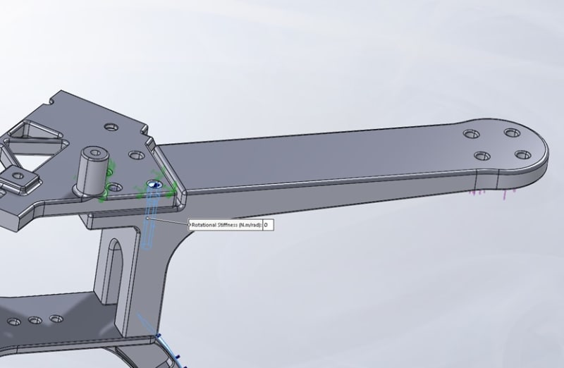
The arm has a 10N load acting upwards at the end, while the top surface of the main body is fixed. This is to simulate the forces occurring when the drone accelerates upwards at maximum acceleration.
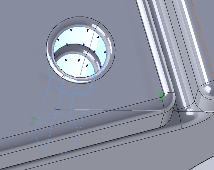
The arms are connected to the main body via bolts. For simplification these have been modelled as pin connections. See below.
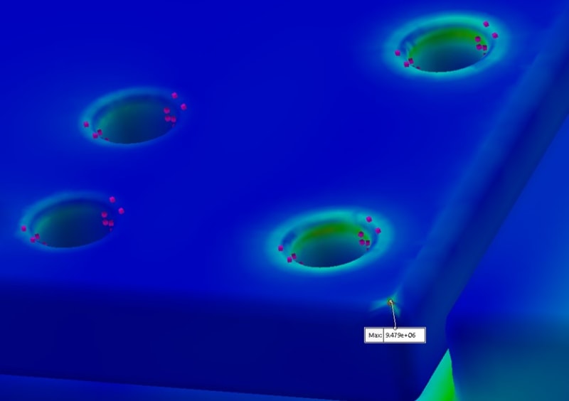
I would like to get an estimate as to how much stress occurs at the bolted connection, to see if the design is suitable. On performing a mesh sensitivity analysis I have found that there is a singularity at the edge of the round. See below maximum mesh refinement and singularity.
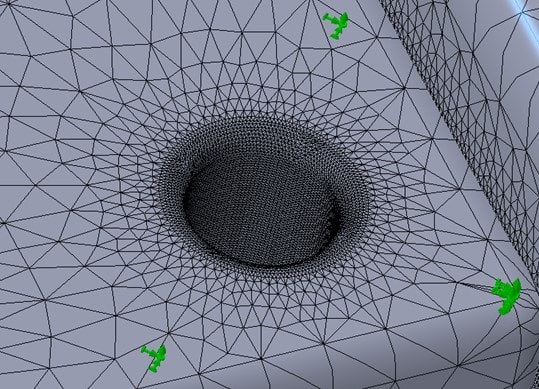
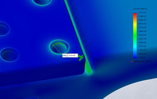
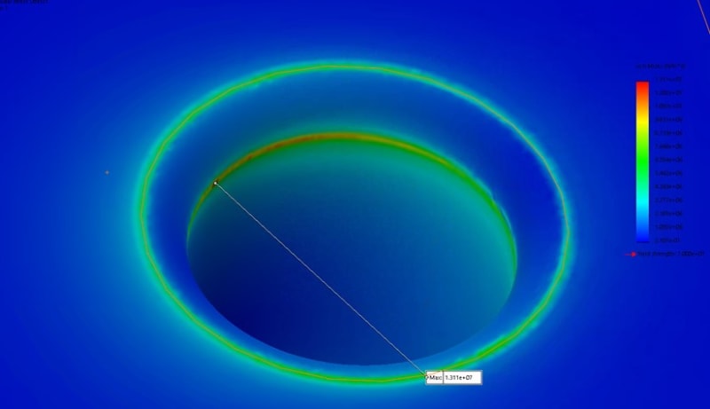
I believe this singularity is occurring as the hole goes from being completely in connection with the pin, to being not in connection at all, essentially creating a sharp edge.
The linear analysis is being run on SOLIDWORKS simulation. I have tried the same set up on Fusion360, getting the same results. Otherwise displacement looks good, and max stress on the arm and max displacement converged many elements earlier, while stress at this bolt hole continues to increase ~linearly.
Does anyone have any suggestions of a better way to estimate the stresses occurring at the bolted connection between the arm and main body?
Many thanks,
Andrew
I am currently designing a drone frame, and performing FEA on a quarter model (see below).
The arm has a 10N load acting upwards at the end, while the top surface of the main body is fixed. This is to simulate the forces occurring when the drone accelerates upwards at maximum acceleration.
The arms are connected to the main body via bolts. For simplification these have been modelled as pin connections. See below.
I would like to get an estimate as to how much stress occurs at the bolted connection, to see if the design is suitable. On performing a mesh sensitivity analysis I have found that there is a singularity at the edge of the round. See below maximum mesh refinement and singularity.
I believe this singularity is occurring as the hole goes from being completely in connection with the pin, to being not in connection at all, essentially creating a sharp edge.
The linear analysis is being run on SOLIDWORKS simulation. I have tried the same set up on Fusion360, getting the same results. Otherwise displacement looks good, and max stress on the arm and max displacement converged many elements earlier, while stress at this bolt hole continues to increase ~linearly.
Does anyone have any suggestions of a better way to estimate the stresses occurring at the bolted connection between the arm and main body?
Many thanks,
Andrew