Continue to Site

Eng-Tips is the largest engineering community on the Internet

Intelligent Work Forums for Engineering Professionals

  • Congratulations IDS on being selected by the Eng-Tips community for having the most helpful posts in the forums last week. Way to Go!

Sinusoidal motion of tool 1

Status
Not open for further replies.

Vxxxxx

Mechanical
Jun 5, 2020
91
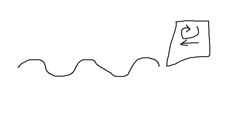
Hi, I am trying to realise sinusoidal motion of my tool and at the same time, my tool is vibrating elliptically.

Right now, I am using Displacement on the reference point of my tool, initial step all 0, step 1 allow X and Y to move.
For the vibration of the tool, I use Velocity with Periodic Amplitude for X and Y respectively.
I input values for amplitude, and I gave a initial speed for X direction to allow forward motion by giving a value for initial amplitude in the Periodic amplitude. For Y direction, I enter 0 for initial amplitude.

(Because in Periodic Amplitude, initial amplitude= initial speed)

However, in order to realise sinusoidal motion of the tool, I cannot give a value for initial amplitude of Y direction, as it will go only one way, which is not what I want as sinusoidal motion requires up and down motion in Y direction.

I thought of using subroutines but there is no subroutines available for Velocity.
Actually I was told that I can realise this motion without using subroutines, and I have seen ax example of a 2D simulation of elliptical vibration cutting in sinusoidal motion.

It would be great if someone could provide some advice. Thank you.
asasas_pj82e9.png
 
Replies continue below

Recommended for you

DISP or VDISP subroutine can also be used to specify user-defined velocity boundary conditions. It may be hard to realize this complex motion without subroutines.

But you said that you have seen an example of such simulation. If you found it in some scientific paper then maybe others described the boundary conditions and amplitudes used for this simulation.
 
Hi FEA way, thank you for your reply.

I wonder if the analytical field could help with this problem.
 
Analytical field won’t work here. It’s used for spatially varying values - different value of some variable at each point of the model.
 
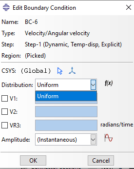
But how do I input subroutine into Velocity boundary condition?

111_fbw120.png


As we can see, there is no 'user-defined' in the options.
However, there is 'user-defined' in the Displacement/Rotation BC.
 
Use keywords to define this type of BC with VDISP:

*Boundary, user, type=velocity
 
@Vxxxxx, you haven't really explained what the problem is using periodic amplitude. As you said, specifying 0 for the "initial amplitude" in the y direction will result in sinusoidal motion in the y direction. Isn't that exactly what you are trying to achieve?
 
Hi, if I specify 0 for the initial amplitude in y direction, the tool will only move in one direction(positive or negative y direction) while vibrating vertically. In order to realise sinusoidal path, the tool should move in both direction (first positive then negative y direction or vice versa) but i can only input one value into the initial amplitude, either positive or negative value.
 
It sounds like you could achieve this centered sine wave with a boundary type=displacement rather than velocity.

Using velocity it will, as you said, move in one direction and then reverse back to the original position.
 
But since I am using type=displacement to control the degree of freedom of my tool(which is constrained as a rigid body), I have to use velocity to realise movement.
 
Sorry, I don’t understand what that means. You may use velocity for DOF1 and displacement or acceleration for DOF2.

You may also continue with velocity on DOF2; just start with the tool in the top or bottom of its travel.
 
I am using Displacement on the reference point of my tool, initial step all 0, step 1 allow X and Y to move(untick box of X and Y).

If I dont do this and I use displacement to move the tool, once the tool in contact with the workpiece, it will deviate from designated path once experienced reaction force from the workpiece since its DOF is not limited anymore.

 
Sorry, I don't understand again. It sounds like you replace a displacement boundary condition with a velocity boundary condition?

If you use any *Boundary to specify the displacement, velocity, or acceleration for a degree of freedom then the motion of that DOF if fully constrained and cannot be altered by external forces.

Is your goal to prescribe the motion (*Boundary) of the tool or are you trying to apply forces and solve for the motion?
 
BC1: ENCASTRE on workpiece
BC2: DISPLACEMENT on tool RP
BC3: VELOCITY (AMPLITUDE X) on tool RP
BC4: VELOCITY (AMPLITUDE Y) on tool RP

So I assign BC2 on RP of my tool, Initial all ticked; Step 1, X and Y unticked, to allow movement in X and Y.
BC3: velocity assigned to RP, X direction with amplitude X (horizontal vibration + initial velocity)
BC4: velocity assigned to RP, Y direction with amplitude Y (vertical vibration)

This is what I have right now, tool vibrating elliptically while moving in X direction.

My goal: prescribe motion of the tool which is sinusoidal motion while vibrating elliptically at the same time.

Sorry I had a typo here:
"If I dont do this and I use VELOCITY to move the tool, once the tool in contact with the workpiece, it will deviate from designated path once experienced reaction force from the workpiece since its DOF is not limited anymore."
 
Thanks for writing it out. The description of your goal seems to match with your description of what you have right now. Can you elaborate on why you think you haven’t achieved your goal?

A velocity boundary condition is just as constraining as a displacement boundary condition. The tools motion will be unaffected by contact with the workpiece.
 
Regarding this sentence "A velocity boundary condition is just as constraining as a displacement boundary condition. The tools motion will be unaffected by contact with the workpiece.", I couldnt agree with you since I had tried using only VELOCITY to my tool RP and my tool path deviated due to reaction force from the workpiece.

I couldnt achieve the sinusoidal motion path simply because I can only input one value (positive/negative) into initial amplitude.
 
A boundary condition of any type is an enforced motion that cannot be violated except for numerical errors. Maybe you had an over constraint somehow, for example if both parts coming into contact are rigid bodies?

If you'd like to share a simplified .inp file then I'm sure we could quickly find the problem. Your goal is not so complicated.
 
Sorry I couldnt share the inp file, but my workpiece is deformable, my tool is created as deformable part but was given constraint as a rigid body later on using *Constraint*.

Lets assume I can assign only velocity to my tool. The problem is still there, I will need to realise sinusoidal motion+elliptical vibration. You mentioned that maybe Displacement can realise this motion but how?

I dont see how it can be done by using displacement.
 
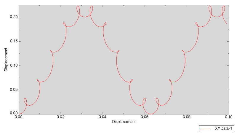
Here is an example of a higher-frequency elliptical motion superimposed on a sinusoidal motion using periodic amplitudes. I think you are trying to do something like this. Maybe it will be helpful. The motion will not be affected by contact unless there are numerical problems with the model.

[pre]*Amplitude, name=Amp-1, definition=PERIODIC
10, 10., 0., 0.1
0., 0., 0., 0., 0., 0., 0., 0.
0., 0., 0., 0., 0., 0., 0., 0.
0., 0., 0.2, 0.
*Boundary, amplitude=Amp-1, type=VELOCITY
RP, 1, 1, 1.
*Amplitude, name=Amp-2, definition=PERIODIC
10, 10., 0., 0.
0., 1., 0., 0., 0., 0., 0., 0.
0., 0., 0., 0., 0., 0., 0., 0.
0., 0., 0., 1.4
*Boundary, amplitude=Amp-2, type=VELOCITY
RP, 2, 2, 1.
RP, 3, 6, 0.[/pre]

plot_gxarbe.png
 
Status
Not open for further replies.

Part and Inventory Search

Sponsor