Continue to Site

Eng-Tips is the largest engineering community on the Internet

Intelligent Work Forums for Engineering Professionals

  • Congratulations IDS on being selected by the Eng-Tips community for having the most helpful posts in the forums last week. Way to Go!

Sinusoidal motion of tool 1

Status
Not open for further replies.

Vxxxxx

Mechanical
Jun 5, 2020
91
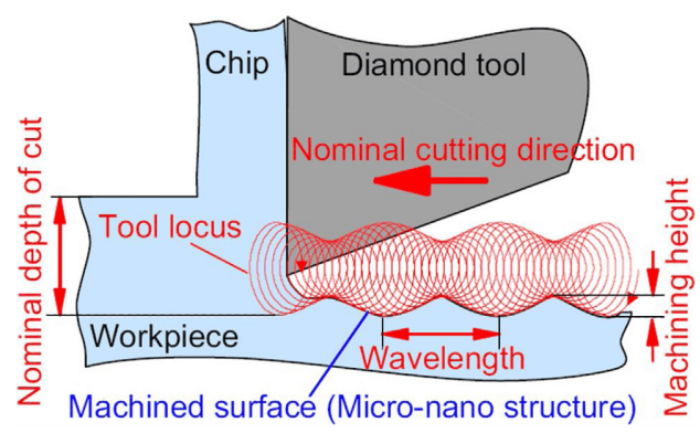
Hi, I am trying to realise sinusoidal motion of my tool and at the same time, my tool is vibrating elliptically.

Right now, I am using Displacement on the reference point of my tool, initial step all 0, step 1 allow X and Y to move.
For the vibration of the tool, I use Velocity with Periodic Amplitude for X and Y respectively.
I input values for amplitude, and I gave a initial speed for X direction to allow forward motion by giving a value for initial amplitude in the Periodic amplitude. For Y direction, I enter 0 for initial amplitude.

(Because in Periodic Amplitude, initial amplitude= initial speed)

However, in order to realise sinusoidal motion of the tool, I cannot give a value for initial amplitude of Y direction, as it will go only one way, which is not what I want as sinusoidal motion requires up and down motion in Y direction.

I thought of using subroutines but there is no subroutines available for Velocity.
Actually I was told that I can realise this motion without using subroutines, and I have seen ax example of a 2D simulation of elliptical vibration cutting in sinusoidal motion.

It would be great if someone could provide some advice. Thank you.
asasas_pj82e9.png
 
Replies continue below

Recommended for you

This is exactly what I am trying to achieve! Thank you very much. But I dont understand what the numbers represent as I can only input 6 numbers into my periodic amplitude.
I dont know what the first number means as well, but from the second to the sixth, they are circular frequency, starting time, initial amplitude, A and B.

*Amplitude, name=Amp-x, definition=PERIODIC
1, 113907., 0., 68.
0., 904.779
*Amplitude, name=Amp-y, definition=PERIODIC
1, 113097., 0., 0.
565.487, 0.

If you could explain what your numbers represent, it would be great as I can modify and fit in numbers for my model.

*Amplitude, name=Amp-1, definition=PERIODIC
10, 10., 0., 0.1
0., 0., 0., 0., 0., 0., 0., 0.
0., 0., 0., 0., 0., 0., 0., 0.
0., 0., 0.2, 0.


And I realised for this code
*Boundary, amplitude=Amp-2, type=VELOCITY
RP, 2, 2, 1.
RP, 3, 6, 0.

you picked two RP, I wonder what it means.

Thank you.
 
I'm glad that's what you're looking for.

The first number (10) is the number, N, of terms in the Fourier series. Abaqus CAE will generate this for you. In Abaqus CAE you just need to right-click and insert additional rows (terms) in the table of A, B coefficients. My example has coefficients for the first row at 10 rad/s and then at the 10th row, 10*10=100 rad/s. See defining periodic data in the manual.

The boundary condition [tt]RP, 3, 6, 0.[/tt] means that degrees of freedom 3-6 on RP will be fixed in position (0 velocity). If you didn't constrain those other degrees of freedom in your model then maybe it explains why your tool motion was affected when it came into contact with the workpiece.
 
You are right, when I was using only velocity, I didnt restrict other DOF and thats why my tool reacted to the workpiece.

As for the A,B coefficients, I dont find the example of abaqus helpful as there is no explanation on how the two coefficients are calculated and how to determine the n (number of rows). I am researching on fourier series coefficients via google and it would be great if you could provide some links on calculation of A,B coefficients and how to use n to realise my motion.

For example,
Elliptical frequency: 20000Hz
X-amplitude: 0.008mm
Y-amplitude:0.005mm
initial velocity (x-direction)
: 50mm/s
sinusoidal motion frequency: 1000Hz
sinusoidal Y-amplitude: 0.05mm

Right now, without sinusoidal motion, I calculated
B= X-amplitude*2*pi*Elliptical frequency (for x-amplitude)
A= Y-amplitude*2*pi*Elliptical frequency (for y-amplitude)


I'm not the best person to explain what a Fourier series is but here is an attempt at your example applied to Abaqus CAE:

It's not required but I would use the same circular frequency for both x and y amplitudes. Set the "circular frequency" to the lowest harmonic frequency. That would be 1000 Hz = 2*pi*1000 rad/s. Starting time=0 (start right away), "Initial Amplitude" is poorly labeled. It is actually a constant term that is added to the series so it is the mean velocity = 50 for your x amplitude, 0 for y amplitude.

First row of A, B coefficients are for the 1000 Hz frequency. For y amplitude choose A=0.05*2*pi*1000 (using your formula). For the x amplitude this row will be zeros.

Second row is for 2000 Hz, Third is 3000 Hz, etc. In your example these will all be 0 until you get to the 20th row (20000 Hz/1000 Hz = 20). In the 20th row you enter the 20000 Hz coefficients (0.008*2*pi*20000). Make sure the x and y amplitudes are 90 degrees out of phase on the 20th row by specifying A coefficient for one of them and B coefficient for the other.

Use 1 in the boundary conditions referring to these amplitudes. Any other value will multiply the already calculated amplitude.

I think that's mostly correct. Clear as mud?
 
Crystal clear, THANK YOU SO MUCH.

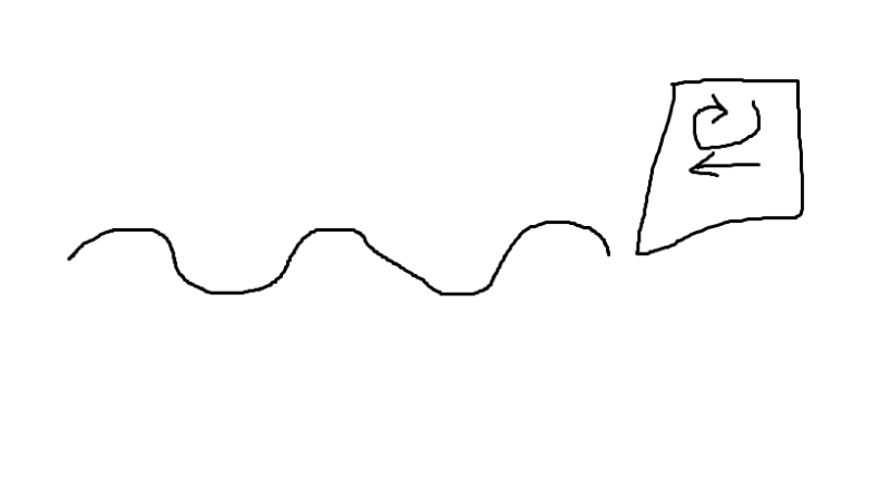
one last question, If I want to vary and control my amplitude throughout the cutting process instead of assigning sinusoidal motion (as shown in figure below), do you have any suggestions?

pic1_odgpex.png


I am planning on using subroutine VUAMP. Thank you.
 
I agree: In this case you will need user subroutine VUAMP.
 
Noted, Thank you very much @OldNail.
 
Status
Not open for further replies.

Part and Inventory Search

Sponsor