Eng-Tips is the largest engineering community on the Internet

Intelligent Work Forums for Engineering Professionals

  • Congratulations waross on being selected by the Tek-Tips community for having the most helpful posts in the forums last week. Way to Go!

Siphon for connecting two reservoir 2

Status
Not open for further replies.

EloyRD

Mechanical
Jan 31, 2013
33
0
0
PE
Hi,

I'd like some opinions about guaranteeing easiness of operation of a siphon connecting two ponds.

The installation is at sea level for irrigation, the configuration is:
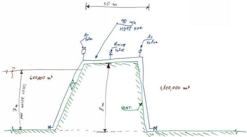
- there is an existing pond of 600,000-cubic-meters of water capacity and 8-meters of water depth. This existing pond has a pumping station of up to 5.2 m3/s and is fed by a 5.6 m3/s open channel.
- my civil engineering colleagues have designed a 1,800,000-cubic-meters pond with the same elevations for bottom and crown of the pond. The design intention is that the new pond increases the water-storage-capacity of the system.

I'm analyzing the mechanism to connect the two ponds. I'm proposing a siphon with piping, a priming valve and air valve at the top of the pipe, and two valves at the bottom of each pond.

My doubts are the following, and I will appreciate any comment about them:
- I am expecting that after priming the system, the two ponds will try to maintain the same water level, with the flow going in one direction or forward as required. Does it works that way?
- Is there a way to operate the submerged mechanical-valves from the surface that isn't an electrical actuator?
- Are regular air valves (like ARI) what I need for this application? I found nothing on their website regarding operation when the water in the inside is below air pressure

Thanks for any opinion.

3840_001_vgkmi7.jpg
 
Replies continue below

Recommended for you

You wrote: "Is there a way to operate the submerged mechanical-valves from the surface that isn't an electrical actuator?"

Yes, One option, very long Extension Stems. However that depends on the Valve type and Valve size.

Sometimes its possible to do all the right things and still get bad results
 
An air vent valve will not work. If fact it will break the siphon by introducing air.

Why would you place any valves underwater? Place them on the surface.
 
You provide a way to fill (not vent!) the siphon the first time (and likely refill it, if flow becomes low when water level goes goes in one side of the other) from the top of the cross-over pipe.

Assume one side is very low - as you draw it above. The water flows out of the siphon but not enough to keep the pipe full, and air refills it by bubbling backwards if the water flow ever becomes less than 100% full of the cross-over pipe.
 
First off I have to ask why you are not simply inserting a pipe or pipes in the bund??

Also at the start point ( may only happen once) please check out the peak velocity and flow from an 8m differential pressure in what looks like a 50m long pipe. This might be quite high!

- I am expecting that after priming the system, the two ponds will try to maintain the same water level, with the flow going in one direction or forward as required. Does it works that way?
Yes providing that the system remains primed and you don't have any non return valves. Flow rate dependent on elevation difference

- Is there a way to operate the submerged mechanical-valves from the surface that isn't an electrical actuator?
Try hydraulic? Or pneumatic. you could do hydraulic by a pump ( might take some time) or bring in an air compressor for a pneumatic actuator. I assume you will need one of the valves ( the lower valve) closed on first fill to fill the vertical leg.

- Are regular air valves (like ARI) what I need for this application? I found nothing on their website regarding operation when the water in the inside is below air pressure
As noted above - NO. There is no such valve - although a vent valve will be useful to break the siphon if you need to. Your vacuum valve / priming valve will be what you need.

The other way of filling this siphon is to close your extremity valves and then pump water in to fill up the entire pipe and then you would need auto vent valves to bleed the air out which either seal on negative pressure or you would just isolate them. Then open the main valves to start flow.


Remember - More details = better answers
Also: If you get a response it's polite to respond to it.
 
Agree with the other posts, the air release valves will not work in this manner.

What are you trying to accomplish? Have you considered using a sluice gate?
 
Thank you all for your comments.

@pennpiper
I was proposing 40-inch butterfly valves, but I have found really high torques for opening unbalanced valves. Now, I'm planning on replacing those with at most 20-inch valve and request a datasheet with low torque.
My issue with the long stem is that for the valve on the existing pond, it will be horizontally at 18-meters of the border of the crown. I can't get an idea in where to put the guides for the stem and how would the operator will reach the handwheel. Maybe I'll just have to explain that they will require a diver to operate that one.

@MikeHalloran
You're right. Those valves are a conceptual fault on my part, I completely misunderstood the concept of air-regulated siphon overflow weirs for small dams that I was using as a reference. Those are gone and on the top I'm only maintaining the priming valve.

@Compositepro
After yours and others comments, I checked my references and found my conceptual fault: I haven´t found air purging valves that seal with negative pressure in the pipe.
About the discharge valve: I understand that to prime the siphon the water leg on the emptier side has to be lower. So, when the water level on the left is at 2.5-meters, I'll require that on the right the leg goes down to the bottom to start the siphon. Hope it makes sense.

@racookpe1978
Thanks for the explanation. I'll now picture better the functioning. I'm getting rid of those valves and only maintaining the priming valve.
 
@LittleInch

Thanks for your answers.
The civil engineer does not have information about the earth dam or the geomembrane and doesn't feel safe about modifying them. The client has a really small window to empty the reservoir of 5-days a year and we haven't found a construction process that works in that lapse.

I'll check on pneumatic actuators for underwater use. Not sure about using oil near water for irrigation.

Thank you for the comment on my request for an air release valve that works on negative pressure. I'm fond of them for gravity pipelines, but I was completely wrong in proposing them in here.
 
@bimr

Thanks for commenting.

My design intent is in providing a way to start the siphon in any direction even when the water level in the fuller pond is at 2-meter.

For the existing reservoir, my issue is in finding a way to operate the valve from the surface, as the valve isn't near a vertical wall that will allow me to use an extended stem. I'll check on the sluice gate, but from the pictures I'll probably have the same requirement of a wall to properly install the guides. Am I wrong?

Thanks.
 
Some other points to consider:

1. Make sure the pipe is reinforced to accommodate vacuum conditions. This may require reinforcement rings.
2. At the elbows at the top of the dike, you may experience cavitation that will erode the pipe and eventually cause it to buckle as the wall thins.
3. Is getting power to the site an issue? If not, you could investigate use of a vacuum pump to start the siphon. This would be much more economical than a pumped water system.

These points are all based on experience with circulating water piping (60" - 84") going over the Mississippi river levee systems in various parts of Louisiana, USA.
 
If the ends of the legs of the siphon pointed straight down-ish into a shallow concrete cup, then priming could be as simple as pumping water to fill the cup on the low end, and using a sewer sucker truck's Roots blower to evacuate the siphon through the vent valve.
I.e., no foot valves required.


Mike Halloran
Pembroke Pines, FL, USA
 
The only reason to place valves on the end of the pipe is if you expect the water level in either reservoir to to drop below the the pipe, so you do not lose prime or to establish prime (filling of the siphon). As long as both ends stay underwater they are not needed. If one side might go dry, you could deal with this by simply adding a u-bend upward at the end of the pipe so that the siphon does not drain out if the end is exposed to air. The U-bend could even go under ground level.
 
EloyRD:
I wouldn’t want the second (larger, 1800k m3) reservoir to start to fill until the first (smaller, 600k m3) is full. Both reservoirs half full just adds a great deal to a surface evaporation problem, a water conservation and pumping volume issue. For that reason the up stream end of the siphon can be (needs be) only a meter or two below the top surface of the smaller reservoir, except to control an intake vortex which might break the siphon. The outlet end of the siphon is a meter or two lower, and does have a cap or valve for closure. I would probably use several smaller dia. pipe siphons, the sum of their cap’y. being slightly larger in the incoming water pumping cap’y. (5.2 m3/sec.). The smaller pipe, fittings and hardware is probably more readily available. The civil guys are designing this newer/larger impoundment, so what do you mean, “The civil engineer does not have information about the earth dam or the geomembrane and doesn't feel safe about modifying them.” Do you mean, they are too damn lazy to do a little more work to make it easy on everyone else. If he’s digging on the low side of the dam, he better know about the dam construction. I’d design a wide spillway 1-2' below the high water mark on the smaller reservoir and also slope the bottom of the new larger reservoir to a deeper area in the middle of the larger reservoir, so it can be pumped dry, if and when not needed. The deeper middle area minimizes the depth in the immediate area of the levee/side berm/dam and reduces surface area when not in use. Would a couple large air bags work as siphon end stops/plugs, doesn’t the pipeline industry sometimes use these as plugs in pressurized pipe lines? Pump the siphon full, then pull the submerged inlet end air bag first, release a little air pressure on the outlet end and that bag will be blown out for retrieval. You do need a downstream spillway and energy dissipating system of some sort.
 
@dhengr

Thanks for your comments. I'll check with the civil guys the proposed option and I'll investigate further about air bags as caps, it seems like a really good idea for my application.

The expression that you commented is related to the option of connecting the bottom of the two reservoirs (existing and new). From what they explained, there is no information about the compactation or type of soil of the dam of the existing reservoir and they have found around it a lot of filling non-classified soil.

For the new reservoir, they have surveyed the soil to locate appropriately. But I'm not sure about their concept of the bottom geometry.

@bimr
I'd check my available losses to see what options of valves I have for flow-control in the siphon.
 
Remote operated subsea shutdown valves are routinely used in subsea gas and oil wells - these are often hydraulically operated, but an air operated option shuld be possible too. The terminal valves may be plain on-off valves, and a modulating valve could be installed at the top of the dyke to control transfer flows, especially when you have a large level differential, else you'd shake the transfer pipe to death with high velocity flows.

Cannot tell if there is a risk of water going below its saturation vapor pressure at the top of this pipe, and causing water hammer as the vapor bubbles collapse going downhill - may be prudent to get some one to run some calcs on this - the modulating valve may need to be shifted to the bottom of the 1.8e6 m3 pond if so.
 
Status
Not open for further replies.
Back
Top