Continue to Site

Eng-Tips is the largest engineering community on the Internet

Intelligent Work Forums for Engineering Professionals

  • Congratulations KootK on being selected by the Eng-Tips community for having the most helpful posts in the forums last week. Way to Go!

Sistering gable end truss with LVL beam?

Status
Not open for further replies.

Nicolas P.

Mechanical
Apr 23, 2021
8
Hi everyone,

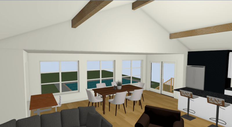
I need to open a gable end wall with an existing vaulted ceiling to include an existing addition within the open floor space (it is currently separated with the old house exterior wall). I have already sized the beam that will be required to support the roof beams. That new beam needs to be flush with the addition ceiling, which is a standard 8’ flat ceiling, as per the picture below:
beam_opening_yguvqc.png


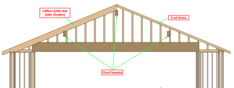
Now, I assume this vaulted ceiling may be a retrofit, as the current gable end framing up top is made of a gable end truss (2x4’s on the flat) such as the picture below, instead of 2x4’s at right angle with the wall face:
roof_beams_-_end_truss_xf5psu.png


Where I’m a bit in a pickle is how am I going to support that gable end truss without modifying it (I prefer not modifying trusses) ?
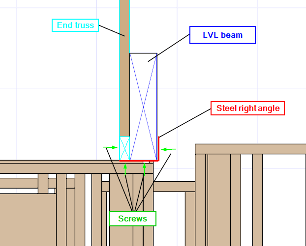
What I was thinking is to sister my LVL beam next to this gable end truss and bolt a steel right angle on its side to it to support the truss. I did not like the idea to rely on nails or screws through a 2x4 bottom chord:
truss_diagram_qclx2a.png


Anything I’m missing from a structural standpoint?

I would still nail/screw the end truss to the LVL from the side through the bottom chord for lateral movement, and through the steel angle in the bottom of the truss as well.

Am I pushing this too far? Should I just nail the truss (bottom chord and webbing) to the LVL without the steel angle?
 
Replies continue below

Recommended for you

I’m a little confused here. Are you removing a shear wall?
 
Hi JLNJ,

I am indeed modifying a shear wall, although I meet all the code requirements in this part of the country (Quebec city, Canada), considering that:

[li]My building is 1 story, 30'x28', and not supporting a top floor[/li]
[li]My location's seismic spectral response acceleration Sa(0.2) is not more than 0.70 (mine is 0.502) and the 1-in-50 hourly wind pressure is less than 0.80 kPa. (mine is 0.41kpa)[/li]
[li]The opening in the wall as shown above is 22' wide, leaving on each side a 4' braced wall panel.[/li]
Then I meet the following requirements of the 2015 NBC:

[li]Minimum total length of all braced wall panels in a braced wall band not supporting a floor is [25% of length of braced wall band] (article 9.23.13.5)[/li]

- I'm keeping a total of 8' of braced wall, out of 30' wide = 26.6%​

[li]The Maximum distance between required braced wall panels measured from the edges of the panels is 6.4 m (article 9.23.13.5)[/li]
[li]The maximum distance between adjacent required braced wall panels in a braced wall band, measured from the edge of the panels, may be increased to 7.3 m provided that, throughout the height of the building, the length of any braced wall panel within the braced wall band is not less than 1.2 m. (article 9.23.13.7 - item 4)[/li]
- I'm at 22 ft, which is 6.7m, with both braced wall panels on each end being 4' (or 1.2m)​

Additionnally, I have an interior braced wall 12' from that exterior wall that goes across the whole building with a single door opening, which also add to the shear strength of the building.

Admittedly, I'm on the edge of what's permitted in the building code, which is why I was looking for the input of fellow engineers as to what would be the best approach for this flush beam application. Perhaps I should lengthen the beam to build a "portal frame" structure?
 
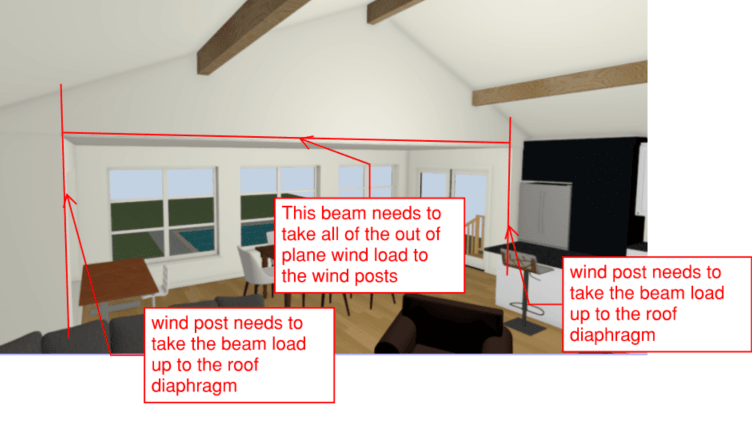
I'd be less concerned about the shearwall or the gravity honestly. My concern would be out of plane wind load. You are going to need some fairly substantial wind beam at the top of window and wind posts at the sides of the opening.

You haven't indicated any real sizing, but supporting that much roof on an opening of that size will need a substantial beam as well for gravity loads.
 
Hi jayrod12,

The roof beams in the picture are existing triple 2x10's and are only supporting 12' of the building's roof, with the rest of the house being trusses. Even so, the beam would be a double 18" x 1-3/4" LVL, so pretty substantial in fact due to heavy snow loads around here.

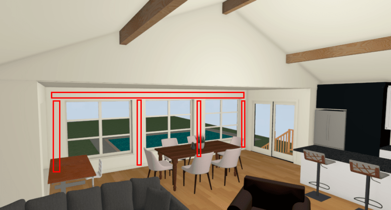
As for the wind beam and posts, I assume you are refering to the framing members on each side of the windows as shown in red below, or something else?
windbeams_r5pcp9.png

If so, to be honest I haven't really looked into that as the addition is already existing (built in the 80's) and doesn't show any sign of structural issue...I will still have a quick look at the perpendicular wind loads just in case.

I have edited my initial post, as I just read it again and saw that I refered to a "new addition" whereas really it is more knocking down the wall and make that addition part of the open floor plan.
 
I kind of mean those red members, however you have to take the out of plane wind loads up to the roof diaphragm.
Screenshot_2021-09-30_074706_xakyrb.png


Also, a 2 ply 18" deep beam really isn't that substantial of a beam. But I'm not running any numbers.

Remember that due to the size of this opening, deflection will be the kicker. And code minimum deflections are still visible on an opening of that size. I can't count how many times I've been somewhere with openings like this that look like they're smiling. Do the beams meet L/360, sure, but L/360 on a 20 foot opening is almost 3/4 of an inch. Seems small, but trust me your eyes can see it.
 
Nicolas P:
It’s up to you to determine the existing loads plus any new loads on that gable end truss, and account for them in your new design. Those type trusses are really not spanning trusses, they just bear on the gable end wall, and the loads are carried by the vert. web members. Roof loads and lateral loads are transmitted through the bot. chord and to the top pls. of the gable end wall. I would nail or screw the bot. chord and the vert. web members directly to the larger LVL in proportion to their loadings, wherever that truss has to span. It is really not some sort of a composite member arrangement. Then the LVL and its bearings, etc. get designed for the loads from the truss, including the eccentric load application.
 
Jayrod,

Thanks for your advices, I will analyze this wind beam/post design requirement carefully with a colleague of mine. As for the beam, I looked at my spreadsheet and it actually called for a triple (not double) 18" LVL beam, which yields a live load deflection of L/716 (0.388"). The snow load used is 55 lbs based on the code SL for the region.

dhengr,

thanks for your feedback as well. Only screwing/nailing was my initial thought as well, I'll have to check for the nailing/screwing pattern that would be required for this once I am settle on a design for the beam...I'm thinking that I could take out the bottom chord and basically build a stick-framed gable end wall over the beam and nail what's left of the web members to the new 2x4's. That would get rid of the small eccentric load.
 
If you could detail the new LVL to act compositely as a chord for the flat roof diaphragm, I reckon that could stiffen up the load path for the out-of-plane wind getting out to the posts. You could even sheath the ceiling for good measure.
 
I agree with bones that would be a reasonable way to deal with the out of plane wind loads I was worried about. I've had to employ that solution on other projects.
 
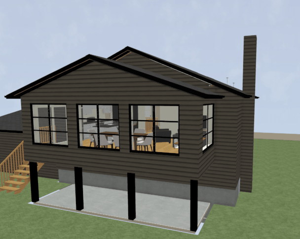
The flat ceiling actually has 3/12 trusses over it like this:

sunroom_jsenxj.png


I'm thinking of a way to brace the 4 roof trusses of the addition together, as well as with the beam, mainly the compression edge.

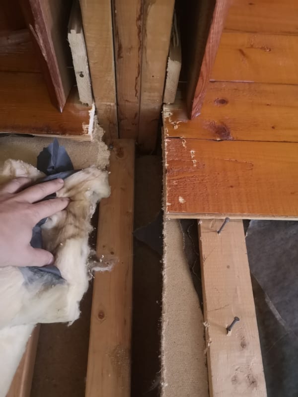
I went to the site today to see how everything is built now that walls and ceiling are being stripped down for this renovation...It is actually quite alarming to see how this was built back in the 70s...The 3 roof beams (triple 2x10's) are each supported only by a 2x3 on the flat (which has bowed toward the interior), barely toe nailed to the wall top plates:

IMG_20210928_121423_iu7cne.jpg


Also, the addition walls that are perpendicular to the main building are not even tied to the actual framing. There is 1/2" space between the first stud of the addition and the old sheathing of the house. This definately needs to be fixed!
 
Status
Not open for further replies.

Part and Inventory Search

Sponsor