Eng-Tips is the largest engineering community on the Internet

Intelligent Work Forums for Engineering Professionals

sistering joists/stair framing

Status
Not open for further replies.

wag2483

Structural
Oct 28, 2009
11
0
0
US
Hey folks,
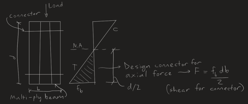
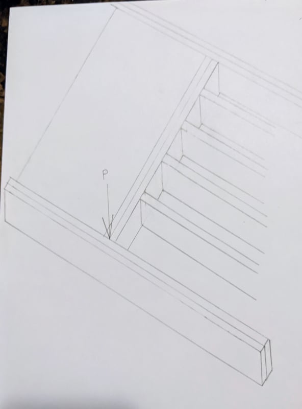
I have an old house, single header and trimmers around the stair opening, the age is beginning to show. I considered sistering the joists and reviewed a few previous posts on this site regarding that topic. Given that NDS doesn't have provisions for sistering and the existing cross section of the joists are no longer available, I'm leaning towards temp framing beneath the tail joists and new double headers and trimmers. That said, the original question comes full circle. Even with consistent EI values, how is a connection developed with double trimmers and headers in modern construction? It seems that these doubles are nailed together without thought, and no guarantee the inner trimmer is sharing the header load with the outer trimmer.
 
Replies continue below

Recommended for you

I use a method that has worked in the past, which is a 1/2" thru bolt at 16" OC, staggered at top and bottom. I never calculated it. The validity comes from this method working in the past, which is a valid form of engineering.
 
The load is not significant so just (2)10d @ 16" o.c. usually works just fine. 1/2"Ø thru bolt @ 16" O.C. is overkill.
 
@XR250 OP had a concern about the middle joist not working compositely, so a thru-bolt would solve that. 1/4" thru bolt can work as well; just didn't want to specify it too low, in case it's really a heavy LVL thing.
 
For sistering you can calculate the shear flow and required nailing to ensure they work compositely. I frequently do this for strengthening existing members for new mech units.
 
Yeah, I think you can get the shear flow at the point of the connection, i.e. about 1.5" from bottom or top of member.

Probably a stupid question...but why does shear flow consider the shear rather than the moment? I always thought it was weird that I was taking the shear at the reaction points rather than the center of the beam, which is the max moment but zero shear. I'd think that the zero shear point needs composite action the most.
 
I'm not sure shear flow is the correct term to use here. It usually relates to members that are stacked vertically and need to be connected such that they act compositely (don't slide against one another like a stack of printer paper in bending).

For a 2-ply beam with the load supported by one piece, I would just design a connection capable of transferring half the load to the other ply (over some reasonable distance).
 
milkshakelake said:
Probably a stupid question...but why does shear flow consider the shear rather than the moment?
I've often been confused by this as well. I believe the shear flow is a result of the change in moment over the length of the beam (which is what shear is). If you grab a stack of printer paper and let the full stack bend between supports at the ends, the shear flow is greatest where the pieces slide against one another the most. At the middle, this should be minimal (technically zero) and at the ends, the greatest. Now if you were to glue the individual pieces together and the glue had adequate strength to resist this shear flow, you would create a significantly stronger beam versus the 500 individual pieces.
 
Ah that makes sense. To get half or one third of the load to transfer, you could draw the T/C stress block at max moment and get the "axial force" in the tension or compression block, then design the bolt/nail/screw for that shear force. Kind of like with concrete Whitney stress block, but simpler.

@Eng16080 That makes sense, but it also makes me wonder about when people add a WT that's about 3' shorter than the main beam on each side. I'd still use max shear in that case, though you'd probably only need it where the WT ends, which would reduce welding a bit.
 
milkshakelake, Maybe I misunderstand. I was thinking this was just a multi-ply beam supporting another beam which frames into its side. If that's the case, I would design the connection to simply resist the vertical reaction from the beam being supported.

For the WT connection, where it stops short, I would try to design the end to transfer the portion of the shear force that it's resisting. Seems a little tricky though. Might need to think about that one more.
 
@Eng16080 You don't misunderstand, we're on the same page in terms of what we think the situation is. I think reaction doesn't account for the tension and compression forces in the beam itself, which are in a different direction. Shear would probably be zero at the point I'm talking about.

Screenshot_2024-02-08_183107_vyybcc.png


Of course, divide that load by number of plies.
 
wag2483, To answer your original question, I would use a double joist hanger to connect each end of the double header to the double trimmer, rated for the load P. Then, I would design a connection to transfer the load P/2 from the inside ply to the outside ply of the trimmer. This connection between plies might even be accomplished by the joist hanger connection assuming the nails/screws are long enough to get into the outer ply. If necessary, the connections mentioned above by milkshakelake and XR250 should provide more than enough extra capacity.

milkshakelake, I don't think it should be necessary to transfer the axial force shown in your cool sketch. Are you saying that's the force acting on the connection due to the beam elongating due to tension (or shortening due to compression)? If so, I think the change in length would be very small/insignificant. Also, if you created a connection with horizontally slotted holes (which can't resist that axial force), the connection would still work.
 
@Eng16080 I think I understand what you're saying. You transfer the shear through the connectors, which would load all the members in flexure. Makes sense.
 
I think I would do it differently.

The individual members of multi-ply beam will deflect identically, if connected properly. if the load is a uniformly distributed load, then I would design the connection between two members proportional to their EI values (equal if they are the same section). If it's a concentrated load, it's a little different animal, but the deflection compatibility still applies. I've modeled sistered joists with fasteners @ 12" and the results are comparable to hand calcs, again, with the exception of the fastening of the two members with a concentrated load. The sistered joist does not have to go to the support as long as a single joist can handle the shear. If one stiffens an existing joist over 90% of the span, they will behave (deflect) almost like two full span joists. That will make the connection to the supports easier and less costly.

My two cents.
 
Status
Not open for further replies.
Back
Top