Eng-Tips is the largest engineering community on the Internet

Intelligent Work Forums for Engineering Professionals

Size of Air Conditioner 1

Status
Not open for further replies.

RM12

Mechanical
Jan 29, 2024
29
0
0
US
I have a large hollow carbon steel cylinder with 58-inch ID, 66 Inch OD and 144-inch length weighing 2342 lbs., inside a 144*144*144 cube. On one face of the cube is attached an AC. The Inside surface of the cylinder is 350 F. I need to calculate the size of AC to use to bring the temperature down to 200 F. The air flows over the cylinder and exits out on the opposite side through a vent. This cylinder generates 500 hp of heat which is the cause of 350 F temperature.
Can anyone help solve this?
IMG_0708_qgwdpl.jpg
 
Replies continue below

Recommended for you

(MintJulep)
Do those fans have data sheets?

Nope, could not pull the data sheet because the nameplate was missing and no indication of what kind of fan it is.
 
Wouldn't the motor or equipment manufacturer have a cooling solution?

What type of actual application is this? If there are 500hp waste heat, and we assume 90% efficiency, that would be a 4,500 hp motor. I would think an application that large gets a professional design by the OEM and not a DIY solution. You also need to dissipate the 500hp + compressor power somewhere.

I don't know what you mean by "core" of the motor. Motors have rotors, stators, windings etc. that all have temperature limits. You don't have control over heat transfer within the motor. the manufacturer will have requirements on the conditions at their interface to the outside (outside the motor). i suspect a motor that large may have integrated sensors and that is why you know the temperatures? You might want to use those to control cooling.
 
mojo97,

Can you please stop drip feeding vital bits of information. Post a proper dimensioned diagram of this motor and supply proper information.

This hollow cylinder you refer to in the OP does not appear to be solid. As solid cylinder 58" ID, 66"OD 12 feet long would weight 16.5 tonnes, not one tonne. So what is it made of? How does heat transfer from the inside to the outside?

Is this actually a 500HP electric motor? in which case your heat output is probably about 50hp or less.

You don't need AC here, you just need some bigger fans, but there is no way this core is outputting 500hp / 375 kW.

Without establishing the actual design data, no one will get anywhere other than wild assumptions and calculations using data which is patently incorrect.

Remember - More details = better answers
Also: If you get a response it's polite to respond to it.
 
The inlet temperature was 78 F and exhaust was at 135 F. With this system the temperature of core came down to 267 F.

Regardless of my calculations, this actual, useful, information that you've been hiding already answers your presumed question; you'd need inlet air close to 0 degF to get the core down to 200 degF. There is no conventional A/C that would get you air that's below freezing.

If nothing else, you could at least get some measurements of airflow to figure out what your apparent heat load is; you have inlet/outlet temperature and if you had airflow, you'd have a much better idea how much heat you're removing as well as how efficiently.

TTFN (ta ta for now)
I can do absolutely anything. I'm an expert! faq731-376 forum1529 Entire Forum list
 
The details are drip fed at customers information leaking speed.

Anyway, I found out the core is 30 inches in length. So basically, the cylindrical area of focus is 2*pi*r*l. The core is carbon steel.
Any other cooling system is not an option because of space constraints.
I do not have the data for air flow CFM and been asking for it for a while.

Appreciate the help.
I did attach a drawing to the OP.
I understand how the problem has been thrown every which way.
 
Regardless, you really don't have many options
> Refrigeration unit to cool inlet temp closer to 0 degF -- that seems absurd, since it'll likely be several times the volume of your box and probably require more maintenance, although, transferring the maintenance risk to something that has to stay online might be worth it.
> MASSIVELY increase the size of the fans -- but reliability/noise/vibration will get worse
> Attach fins to the cylinder to massively increase the exchange surface area -- this seems the simplest thing, assuming it hasn't already been done

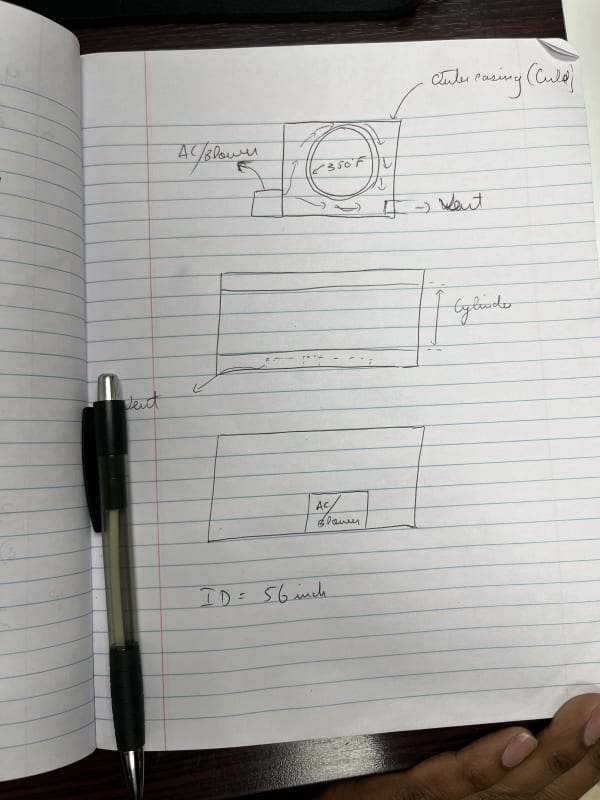
you got an ostensible 80 degF drop with your existing setup, so that's doing pretty well and I would focus on that, rather than the supposed power consumption, since the deltaT is a measured fact and does not assume any data not in evidence, other than a presumed 350 degF apparent source temperature. Using that, doubling the efficiency of whatever is doing the heat transfer will hypothetically get you to the desired surface temperature, such as doubling the heat transfer area or doubling the air flow, or dropping the inlet air temp to 0 degF. You just have to pick your poison and live with the consequences.

TTFN (ta ta for now)
I can do absolutely anything. I'm an expert! faq731-376 forum1529 Entire Forum list
 
Let me know what is wrong with these steps:

Calculate the heat rate using the inlet and outlet air temperature. I will assume any existing CFM AC. Example 4000 CFM
Heat loss rate = Mass flow rate x specific heat capacity of air x Delta T

For this particular heat loss rate calculated we can determine what the outside surface temperature to be when the inside surface of the core is 200 F. Thermal conductivity of carbon steel is used.
Use this to outside temperature and inlet air temperature to determine what the heat transfer coefficient is for convection.

From the heat transfer coefficient find what the velocity of air is using the empirical formula.

Keeping this aside before we determine if that velocity is enough, we calculate with the current CFM how fast does the temperature go down. If its too slow then we can probably think of a baffle design to increase the velocity and improve the heat transfer.
If that doesn't work either we increase the CFM and re do the steps.
 
Older designs likely used experience of how many fins etc. a motor needs to have and what airflow is required. Modern designs may use CFD and heat transfer analysis in addition.

For a simple TEFC motor they basically had the housing with fins and the fan and at a given ambient temperature "that works". it isn't a simple equation to "assume" a coefficient and calculate heat transfer in a complex system. Velocities and turbulences will be all over the place depending on location.

Even if you cool your "cylinder" to 200°F, is that cold enough for the motor? Does it have a 200°F ambient rating?
 
I understand this. It's an odd situation I haven't been on the site so pulling information like if it has fins on the casing or not is not easy. I don't have the nameplate information either. The one they sent is blurred.
I am told for some reason the motor started operating at 350 F and it needs to come down to 200 F inside (don't know if it's the ambient temperature).Many a times when a motor starts going haywire manufacturers change its ambient temperature based on application and customers situation. I was also told the cylinder likely has no fins and I can see that because many high voltage motors have no fins but internal fans on the rotor and a vent.

I haven't assumed a coefficient for heat transfer. I only back tracked calculated it, assuming a CFM for a 15-inch radius duct.

That would give you an insight of the how flow might be.
 
Let me know what is wrong with these steps:

Calculate the heat rate using the inlet and outlet air temperature. I will assume any existing CFM AC. Example 4000 CFM
Heat loss rate = Mass flow rate x specific heat capacity of air x Delta T

Or Q = 1.1 (CFM) (delta T) at standard conditions

For this particular heat loss rate calculated we can determine what the outside surface temperature to be when the inside surface of the core is 200 F. Thermal conductivity of carbon steel is used.
Use this to outside temperature and inlet air temperature to determine what the heat transfer coefficient is for convection.

There are many assumptions here:

Assuming an inside surface temperature and outside surface temperature of steel the heat flow is Q

Q= KA dT/dX For the thinckness of the steel cylinder

K is know for steel but what is actual heat transfer area? Heat is being transferred mostly around the core area to the outside but it is being transferred horizontally from the core area along the length of the cylinder first then to the outside so heat transfer is not just one dimensional.

Also heat transfer across outside surface film is

Q = UA (delta T)

Again most of the heat tranfer area is in the center around the core, and conducted away from the core to the cylinder then transferred by convection outward so A versus delta T is not really known. Also the delta T is not just the metal surface temperature minus the mean of the air temperature but the long mean temperature difference. There are handbooks that give calculations for the LMTD based on different flow configurations such as parallel/counter/cross flow configurations, but for such a large single cylinder I don't know if there is any calculations.

From the heat transfer coefficient find what the velocity of air is using the empirical formula.

Again things are not very symetric here. Some surfaces the air is blowing over very fast but some surfaces the air my not be flowing much at all depending on where the fans are located.

Keeping this aside before we determine if that velocity is enough, we calculate with the current CFM how fast does the temperature go down. If its too slow then we can probably think of a baffle design to increase the velocity and improve the heat transfer.

You lost me here. You already know that with the current CFM the temoerature in the core is still too high.

If that doesn't work either we increase the CFM and re do the steps.

I would also look at rearranging the air flow so that all surfaces are exposed to the blast of the air flow from the fan. You could duct the outlet of the fans to all sides of the cylinder surface. Also check for best location of the outlet so air flow path maximizes LMTD.
 
After many back and forth clarification queries, here is the true problem. The rotor of the motor is equipped with a fan and moves air axially through the stator. The inlet air temp is 78f and outlet air is 135 F. The material of the core being cooled down to 200 F from 350 f is carbon steel.
 
Status
Not open for further replies.
Back
Top