Continue to Site

Eng-Tips is the largest engineering community on the Internet

Intelligent Work Forums for Engineering Professionals

  • Congratulations KootK on being selected by the Eng-Tips community for having the most helpful posts in the forums last week. Way to Go!

Size of the hole @ MMC 3

Status
Not open for further replies.

Azzazil

Automotive
Feb 1, 2020
95
Hello guys,

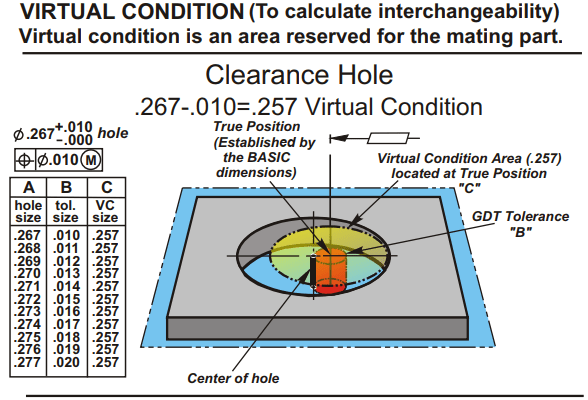
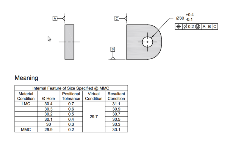
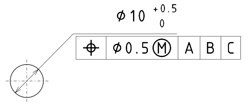
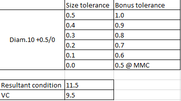
I have struggle with acceptance criteria for hole, you can check dimensions on picture and calculation.
Through calculation I can see that for hole diameter of 10.2 mm I get bonus tolerance for position to 0.7 mm, by rule when I get bonus tolerance it means that I get increased positional tolerance but I increase also the size of the hole. Which means that I can accept hole with diameter of 10.9 mm in this case (10.2 + 0.7 = 10.9 mm).
With calculation I can see that end result with biggest bonus tolerance of 1 mm I can accept hole with diameter of 11.5 mm, did I understand this or I misunderstand something?
diameter__mnu6sd.png

excel__umsxpl.png
 
Replies continue below

Recommended for you

Azzazil,

Bonus tolerance only allows for additional variation in location due to size variation - not the other way around. Your limits of size may NOT be violated. Your Virtual Condition may also not be violated which is a boundary of fixed size 10-0.5 (MMC size of 10 minus your geometric tolerance @MMC) = 9.5 fixed at your true position (basic location with respect to your Datum Reference Frame A|B|C).

I assume by the terminology Resultant Condition/Virtual Condition you are going by ASME - bonus tolerance actually does not appear anywhere in the standard, this is just an easy way of visualizing/calculating the additional position tolerance allowed by the MMC concept. The only requirement is that the feature must not violate your Virtual Condition, bonus tolerance is just a result of the fact that a hole @ LMC may have more location error than a hole @ MMC while not violating your VC (ie: imagine your VC as simulated by a pin - if you put a part with a larger hole over the pin then a part with a smaller hole, the larger hole would have more movement - this is essentially your allowable position variation).

Through calculation I can see that for hole diameter of 10.2 mm I get bonus tolerance for position to 0.7 mm

"Bonus" would mean anything beyond what is stated in your Feature Control Frame. In this case your maximum "bonus tolerance" is actually 0.5 , the "bonus" is a result of your allowable variation of size which is 0.5 . That means the maximum possible location variation is geometric tolerance + bonus tolerance = 0.5 + 0.5 = 1.0 .

With calculation I can see that end result with biggest bonus tolerance of 1 mm I can accept hole with diameter of 11.5 mm

Refer to my above. The limits of size may not be violated - your LMC size is 10.5 and your MMC size is 10 , this is not changed.
 
Thanks chez311 for your explanation. It make sense, but other resources confuse me when I google this relation about MMC.

I found also the video on YT where guy explains that if there is increase in positional tolerance than its feature increase its size. You can see from 5:45 explanation why size of hole increase, here is the link Link
 
Azzazil,

Again, the increase in allowable position tolerance is a result of the size variation, not the other way around. Another way to think about it is that your bonus tolerance is a function of the feature size.

All really comes down to is that the limits of size may not be violated, and your Virtual Condition may not be violated. Everything else is a result of those two conditions - this is a bit of a simplification, but its the easiest way of explaining it without going into the weeds.
 
Kind of like that:

Capture_f2aulb.png


"For every expert there is an equal and opposite expert"
Arthur C. Clarke Profiles of the future
 
Thanks again chez311 and CheckerHater for your reply. OK now I get it, feature of size is constrained by size tolerance. If feature of size is getting bigger (inside size tolerances) than positional tolerance is increased but in a way that is possible to fit inside pin that is representation of Virtual Condition plus positional tolerance. Only enigma what is left for me is that why we have Resultant condition like it is calculated in example.
GD_T_MMC_uyo0oi.png


If you visit this site here is also offered calculation of Resultant condition, why Resultant condition is important?
 
"resultant condition" is usually just a step to calculate the remaining wall thickness. It might also provide the diameter of a sealing washer that covers all possible locations and sizes of the hole.
 
Azzazil,

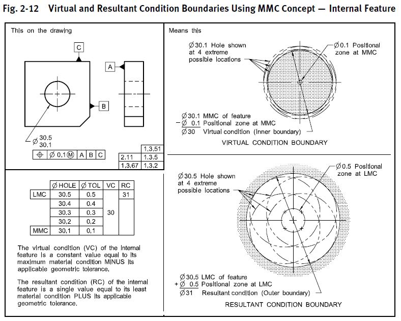
It always helps to refer to the primary document. In your case, I am assuming ASME Y14.5-2009 or 2018. See fig. 2-12 from 2009 below - while Virtual Condition is the constraining or limiting boundary (ie: cannot violate Virtual Condition) the Resultant Condition is just that, the other worst case* boundary which is a result of this condition. For MMC Virtual Condition is outside the material and Resultant Condition is inside the material, for LMC it is reversed. Since it is NOT the constraining boundary (ie: the feature may violate it, but the calculations provide a rough estimation of what this worst case boundary is approximately - see below about my note on orientation/form error) it is usually only used for wall thickness or clearance calculations as 3DDave noted, it is NOT an acceptance criteria for pass/fail of a feature.

Below is the definition from the standard as well.

Y14.5-2009 said:
1.3.51 Resultant Condition
resultant condition: the single worst-case boundary generated by the collective effects of a feature of the size’s specified MMC or LMC, the geometric tolerance for that material condition, the size tolerance, and the additional geometric tolerance derived from the feature’s departure from its specified material condition. See Figs. 2-12, 2-13, 2-15, and 2-16.

fig_2-12_s1bxhd.jpg


*I'm being a bit loose with terminology for sake of simplicity. The simple calculation for Resultant Condition does not take into account orientation or form deviation.
 
Hi chez311, yes it is ASME Y14.5-2009. Anyway now it is much clearer with your explanation thank you :).
 
It's interesting that the standard gives a single value for the Resultant condition and the previous example gives a series of values. Given the definition as the worst case boundary, it's not clear where that other example came from.
 
Prior to 2009, Resultant Condition was given by Y14.5 as a variable number (see pages 30-31 of the 1994 standard). So people would sometimes speak of the WCRC (worst-case resultant condition). Then in 2009 they wised up and defined the RC as a single, constant value.
So Azzazil's graphic seems to be following the pre-2009 definitions.
 
As long as they are consistent. It's another case where I wonder why they redefine what a term means. As I suggested - it's an intermediate calculation for a stand in for a localized wall thickness measurement, so calculation of intermediate values make as much sense as calculation of allowable "bonus" tolerance does. If the worst case is something to know then the intermediate values should also be something worth knowing.
 
Status
Not open for further replies.

Part and Inventory Search

Sponsor