Continue to Site

Eng-Tips is the largest engineering community on the Internet

Intelligent Work Forums for Engineering Professionals

  • Congratulations IDS on being selected by the Eng-Tips community for having the most helpful posts in the forums last week. Way to Go!

Sizing Mitek Truss Plates for Wind Girder 1

Status
Not open for further replies.

Signious

Industrial
Oct 21, 2014
221
Hello,

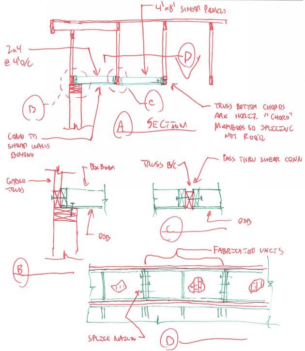
I have been tasked with designing a set of wind girders to transfer high wind forces for residential tall walls under a gable end roof. The system consists of:

38'-0" long parallel chord truss (46" deep) with 7 panels, designed it as a pratt truss out with MSR chords and spf no.2 webs. Truss sits above ceiling sheathing, underneath the first two gable trusses and butts into the third GE truss back.

My question is how do you go about sizing the appropriate plates when the manufacture will not give the design information for the plates? I feel kind of dirty just specifying shear / tension / compression loads at the joints and leaving it up to the roof truss mfctr to size them.

Are there any good publications with minimum values for truss plates? I have the Simpson catalogue plate information, and CSAS347 (useless) but just don't know how their numbers compare to the Mitek product. OS86 really wasn't much help either.

Thanks!
 
Replies continue below

Recommended for you

I doubt you will get any info from Mitek. Can you just specify the loads and have them submit shop drawings for your approval?

When I am working on a problem, I never think about beauty but when I have finished, if the solution is not beautiful, I know it is wrong.

-R. Buckminster Fuller
 
I thought about that, and it is my worst case option - I just feel somewhat scummy as they will chargeback the customer for engineering consultation to do the plate sizing.

Already talked to Mitek and you are correct in saying they will NOT give out any design information for the plates.
 
That is the nature of the beast. If you want to use press plate trusses, you go through the truss Manufacturer who pays Mitek for the software.
 
Where's KootK on this one, he'd love to hear you're doing this detail.

Can't you tell the truss supplier that you want a truss and give them a design load and let them design the entire thing? It would likely end up being more economical.

If you detail your connections and orientations effectively they'll provide you with exactly what you need for the lowest price possible.

Once you start telling them exactly which members to use, they'll likely charge you an increased amount.

A few people have noted in other threads on this sort of topic that the erection of this truss may be difficult as the plates may not survive the out of plane bending/prying.

Would it be more constructable to detail a built-up (2 or 3 ply) 24" deep LVL on the flat?
 
I wouldn't design the plates or any of the truss members. I would just make sure that things work in a span/depth kind of way and give the truss manufacturer the loads and other design criteria. The cost of the plate engineering should be built into the cost of supplying the truss.

I like to debate structural engineering theory -- a lot. If I challenge you on something, know that I'm doing so because I respect your opinion enough to either change it or adopt it.
 
Sorry Jayrod. I posted before I got a chance to read your comments. And yes, I'm wildly excited about the prospect of this detail coming to pass. If Signeous can make it happen, I want details and photos! And some tips on how to be more persuasive.

@Signeous: you'll want to check out this thread if you haven't already: Link.

Jayrod said:
A few people have noted in other threads on this sort of topic that the erection of this truss may be difficult as the plates may not survive the out of plane bending/prying.

I've been thinking about this. I wonder if one could make the truss in, say, eight foot segments and field splice them together with nailer plates.

Go Signeous go!

I like to debate structural engineering theory -- a lot. If I challenge you on something, know that I'm doing so because I respect your opinion enough to either change it or adopt it.
 
You want the truss plant doing the engineering. Engineering wood trusses is all their engineers do and they know far more than we can ever hope to find with internet searches. The engineering cost is not much in a truss package because it is a cut throat industry that is highly automated.

Keep in mind also, even if you provide a detailed plan specifying all the requirements you may find the truss plant will turn around and do whatever they want anyway. We find the wood truss guys are more tuned to working with residential clients and they are far less likely to follow drawings than steel suppliers.
 
Thanks for all the feedback guys, didn't realize gable end bracing was such a hot button topic here.

I followed that thread for a bit Kootk, but missed the last half or so - thanks for the link. Just for the sake of asking - anyone know what software Medeek was using for his FEA? Looks useful for this scope of work!
 
I've had a detail in mind for this situation for some time now. It's something that XR250 and I bandied around a bit in the other thread I think. I invested a few minutes to sketch it up today in case it may actually be of use to someone out in the wild. Obviously, the rats nest of poorly connected kickers will always be the contractor favorite.

20150422_Horiz_Box_Beam_wd9imc.jpg


I like to debate structural engineering theory -- a lot. If I challenge you on something, know that I'm doing so because I respect your opinion enough to either change it or adopt it.
 
So... How was it received? And executed? If you only did it once, that in itself is pretty telling.

I like to debate structural engineering theory -- a lot. If I challenge you on something, know that I'm doing so because I respect your opinion enough to either change it or adopt it.
 
Oh, and the details are awesome Signeous. My complements to the chef.

I like to debate structural engineering theory -- a lot. If I challenge you on something, know that I'm doing so because I respect your opinion enough to either change it or adopt it.
 
The ICC-ES reports have plate capacity values. Google "mitek site:icc-es.org"
 
Couple questions if you don't mind:

First nice thread and solid sketches and details all around.

@Signious What is the DSP for? I mean why is it required? This is like a hold down for the double top plates?

@Kootk -> in your sketch the "4x8" shear panel is really more like "2-2x4", right? as it is is "interrupted" at the first truss?

Thanks!

EIT
 
RFreund said:
@Kootk -> in your sketch the "4x8" shear panel is really more like "2-2x4", right? as it is is "interrupted" at the first truss

Yesir. 22.5" I suppose. Thanks for the fact check.

Although... in another thread someone had the clever idea of making the first truss a double and spacing it 4' in. That might be a good deal simpler for both my detail and Signious'.

I like to debate structural engineering theory -- a lot. If I challenge you on something, know that I'm doing so because I respect your opinion enough to either change it or adopt it.
 
@RFreund

The DSP is to assist transferring overturning moments to the set of double vertical studs, and thru to the foundation thru hold down anchor.

When I ran loads prying action between top plates and the vertical studs was a failure point with LS50 angles, and any kind of nailing or simple framing angle connection was disallowed as nails in withdrawl.

@KootK

I missed that thread, though I fail to see how adding in a girt truss / rigidity to a gable truss will help to transfer loads to roof sheathing and shear walls. Link?
 
dcarr82775:

Thanks, that is exactly what I am looking for!
 
Status
Not open for further replies.

Part and Inventory Search

Sponsor