Eng-Tips is the largest engineering community on the Internet

Intelligent Work Forums for Engineering Professionals

SJI Steel Joist Top Chord Analysis 1

Status
Not open for further replies.

waytsh

Structural
Jun 10, 2004
371
0
16
US
Hi All,

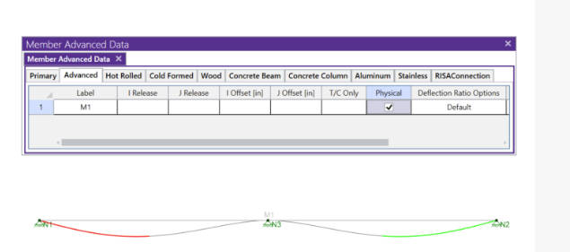
I am modeling a steel joist in RISA and I am curious about what is the correct and/or permissible way to analyze the top chord for bending moments. What I mean by that is that if I model the joist as a whole I am getting different moments for the top chord than if I would model the top chord as an independent fully supported continuous member. The difference is substantial as you can see from this screen shot.

RISA_Joist_Screenshot_wuuzyi.png


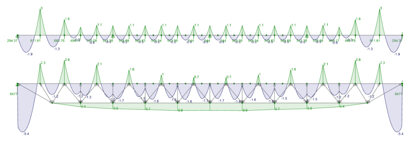
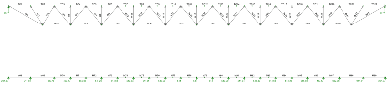
The top diagram is just the top chord as a continuously supported member. The bottom diagram is the chord as part of the entire joist. Which way are you guys using to determine the required bending in your top chords?

Thank you!
 
Replies continue below

Recommended for you

I'd suggest checking out the SJI publications for strengthening bar joists. It is near impossible to get these things to calc out at a component level like you're trying to do. Are you analyzing this joist for a new added load, like a RTU or something? SJI specification allows for all sorts of different K-values to use for joist components and fixities of components.

In my experience, the most common way to analyze these is to consider it a simply supported beam and envelope your shear and moment diagrams with new loads vs design capacities, then reinforce the joist for the deficiencies in bending and shear. There are additional checks to consider as well and they're all covered in the SJI publications.
 
Dave Atkikns said:
Modeling the joist in its entirety will give you more accurate results.

Not exactly true. At least it wasn't a few years ago. There are two considerations here.

Issue #1: The forces and moments reported in the top chord
When I worked for RISA, there was a Global Model Settings - Solution input called "Number of Internal Sections". This was (by default) set to 100. Which means the program is looking at approximately 100 locations for calculation of moment and forces.

That's almost certainly why you're getting different results for the single member vs broken member moment diagrams. The single member model doesn't capture the moment as accurately at the internal joint locations.

Issue #2: How to handle bracing and member code checks
My guess is this might be what DaveAtkins was talking about. It can be easier to specify how a member is braced or unbraced when you use one long physical member. Though I think this is still a matter of preference and user input, as both method can give good results for code checks when handled properly.
 
Does the discrepancy involve the dead load from the remainder of the joist members? If you run just a LL combo, does the discrepancy still exist? I would venture to guess the "whole joist" model is more accurate. But hard to tell with the info here.
 
It's essentially the difference between spring supports (equivalent springs based on bottom chord + web assembly stiffness) versus rigid supports. I think celt83 is alluding to this...

I'm squinting at the image and it looks like the first model has rigid vertical supports at each panel point. I don't think this is a realistic representation of the top chord stress state.
 
Thank you for all the responses. Let me try to address some of your questions/comments.

dold said:
I'd suggest checking out the SJI publications for strengthening bar joists

Yes, for checking the actual capacity of the components I am using the SJI specification along with the corresponding K values. I am only using RISA to obtain the forces in the members and not for the stress checks.

dold said:
Are you analyzing this joist for a new added load, like a RTU or something?

Yes, I am reviewing for some new roof top units and suspended loads.

JoshPlumSE said:
When I worked for RISA, there was a Global Model Settings - Solution input called "Number of Internal Sections". This was (by default) set to 100. Which means the program is looking at approximately 100 locations for calculation of moment and forces.

You are correct. I had the number of internal sections set to 100. I maxed it out to 200 and the end panel moments have gotten closer, but the mid-span moments are still about three times larger on the full joist model than the independent chord model.

cec17 said:
Does the discrepancy involve the dead load from the remainder of the joist members?

The discrepancy involves all load cases.

Celt83 said:
what support conditions did you use in the top chord only beam model?

I used originally had a pinned support at the left and rollers the rest of the way. I have since changed it to all pinned and it did not change any results.

One of the reasons I am asking this question is that according to the original manufacturers design data the bending moments appear to be based on a chord modeled independently. In fact they match the independent chord model almost exactly. SJI has a sentence saying that the top chord shall be designed as a continuous member subject to combined axial and bending stresses. Not sure if they are saying that it can be modeled independently or if they are saying that to just be sure to consider the continuity that exists.

 
I don't believe the intent of SJI saying to design it as a continuous member is meant to be interpreted as modeled independently. I believe the intent of this sentence is for the modeler not to apply member releases to the top chord at the segments between panel points and also to manually set the appropriate unbraced length.

Regardless you could model it independently but the independent and the full model need to be compatible and result in the same stress states. The get a compatible isolated top chord model you'd need to both apply various axial loads to get the correct axial stress state and either determine appropriate spring supports or equivalent intermediate vertical loads. The effort involved to do the above is likely much more than just modeling the joist.

For your joist model it's not clear if you have this modeled as pin-pin but if so recommend pin-roller instead.
 
The most "common" way to analyze these is to punt them back to the joist manufacturer....... just saying. That's not often viable, but heck.
 
Josh, are you aware of any way to get more accuracy out of the full joist model other than setting the internal sections to 200? That seems to be the max.
 
why do you think you need more accuracy out of the full joist model? 100 section slices to generate the diagrams already looks like it is giving you a really smooth plot.
 
waytish said:
Josh, are you aware of any way to get more accuracy out of the full joist model other than setting the internal sections to 200? That seems to be the max.

Nothing that's guaranteed to work. But, you can play with the various settings related to internal vs reported sections. If your joints are evenly spaced, there may be a way to make it so that there is a internal section at every joint. For example, your chord looks like it's essentially 12 equal pieces. If that's true, then if you set the number of internal sections to 13, then it might force there to be an internal section at every one of those joints.... Each of those 12 pieces plus the end joint.
 
waytsh said:
Josh, are you aware of any way to get more accuracy out of the full joist model other than setting the internal sections to 200? That seems to be the max.

Make sure you have the top chord defined as a 'physical member' in the members spreadsheet. [URL unfurl="true"]https://blog.risa.com/post/what-are-physical-members[/url]

Snipaste_2024-09-06_13-48-50_ljp1qx.jpg


Otherwise, you can split the top chord member at the joints so you end up with multiple members, but do not release moments at the ends of the members. Doing this makes managing results a little more cumbersome but will give you more reporting stations.

The user manual discusses this. Search "physical members" in the manual. [URL unfurl="true"]https://risa.com/assets/documentation/General_Reference_3D.pdf[/url]

Snipaste_2024-09-06_13-47-05_myfyom.jpg

Snipaste_2024-09-06_13-45-33_psubsw.jpg
 
dold said:
Make sure you have the top chord defined as a 'physical member' in the members spreadsheet

I believe your suggestion (modeling the top chord as a single physical member) is the SOURCE of the problem I was describing to the OP, not the SOLUTION.

That being said, I have looked at his image on a higher resolution model and I'm not certain that my suggestion was the real problem he was looking at. If the OP had modeled the top chord the same way in both images, then my suggestion of internal vs report sections was probably NOT the cause of the difference.

Rather Dave Atkins had it right from the beginning.... that modeling the entire joist would give more realistic moments in the top chord. Because the top chord forces are affected by the overall truss behavior. In particular the vertical web members don't provide as much support as the diagonal members... which we can clearly see from that moment diagram (now that I look closer).
 
waytsh - I think the first chord-only model is representative of the stress in the top chord if you had shoring props placed at each panel point. I say just delete that model and use the full truss model and you're good to go.

Just as a side note - I've always struggled with how to model the end bearing seat joint. There must be some small eccentricity there, but modelling even a small offset at the end panel point results in very high local stresses. Anyone know how manufacturer's model that area with their software?
 
I actually did have the top chord split into individual members at each panel point and they were defined as physical members in each model.

Joist_Member_Labels_o8m7zt.png


One of the things that seems suspicious to me about the entire joist model is how the negative moment is not fully developed over the verticals like it would be with the fully supported chord. This does not seem to be related to the stiffness of the vertical member itself because when I switch out all these vertical and web members to rigid sections it still occurs.

bones, for what it is worth, the design data I have from the manufacturer seems to show that they ignore the eccentricity at the end of the joists and just bring the end web up to the support. Now they do cut back the span a bit, about 3" on either side.
 
You are still trying to compare two incompatible models.

Abandon modeling the top chord on it’s own and just use the full joist model.
 
I don't actually know, but regarding the seat and the eccentricity, this kind of overstress perhaps doesn't appear in physical testing, or some plastification in this area worked in testing. They may model that element as rigid as it's been shown in testing to be effectively rigid. (As a side note, there's a new reduction factor on 10d nailed posts in shear walls in the SDPWS that nobody much has an explanation, for, but it's been added because it showed up in testing, so I feel that's related and worth mentioning.)

There's a fair bit of research on some of these items and as you probably know, there are differences between AISC and SJI for some of these elements. SJI joists are not 100% designed per AISC because they have found different approaches that are more detailed (last I heard, circa 2001, Vulcraft had about a million lines of code in their joist production program).

I'm speaking extemporaneously on this, based on my recollection, so I don't have any specific documentation to point to. But open web steel joists are not covered by the AISC specification.
 
Status
Not open for further replies.
Back
Top