Eng-Tips is the largest engineering community on the Internet

Intelligent Work Forums for Engineering Professionals

SJI Steel Joist Top Chord Analysis 1

Status
Not open for further replies.

waytsh

Structural
Jun 10, 2004
371
0
16
US
Hi All,

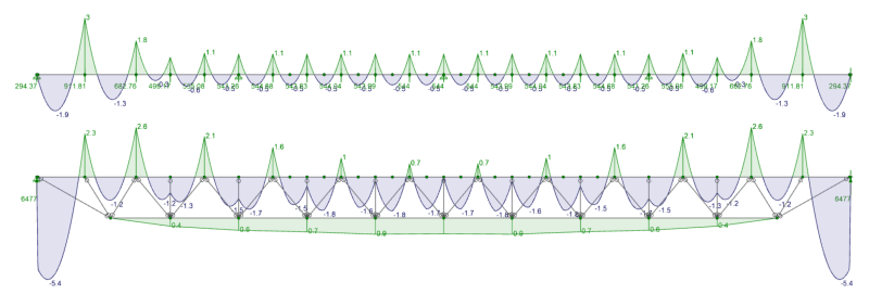
I am modeling a steel joist in RISA and I am curious about what is the correct and/or permissible way to analyze the top chord for bending moments. What I mean by that is that if I model the joist as a whole I am getting different moments for the top chord than if I would model the top chord as an independent fully supported continuous member. The difference is substantial as you can see from this screen shot.
RISA_Joist_Screenshot_wuuzyi.png


The top diagram is just the top chord as a continuously supported member. The bottom diagram is the chord as part of the entire joist. Which way are you guys using to determine the required bending in your top chords?

Thank you!
 
Replies continue below

Recommended for you

I do agree the full model joist is the most accurate and that is what I plan to use. I am just confused why the positive moment is not peaking higher over the vertical web members. Intuitively this does not make sense to me. I would have expected the two results to be a little closer together. Maybe I am just off base.
 
The key difference is the boundary conditions you have set in each model. The chord-only model has vertically rigid roller supports representing the rest of the truss. In reality, those boundary conditions should be springs rather than rollers to more accurately represent the stiffness matrix from rest of the truss members.
 
bones206 has it right. The top chord only model does not account for vertical deflection at each node, as you get with the full joist model. If you knew the vertical deflection at each node, and modeled that as springs in the top chord model, the results would be a lot closer. Although, axial forces induced into the top chord by the diagonal web may also have an effect.

DaveAtkins
 
waytsh:
" This does not seem to be related to the stiffness of the vertical member itself because when I switch out all these vertical and web members to rigid sections it still occurs."

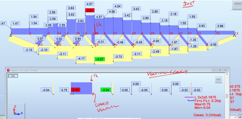
To me the verticals are really acting as load pass through elements, do a virtual work check for a point load at like the 3rd vertical and see how much work the verticals contribute to the overall solution assuming true truss behavior.
 
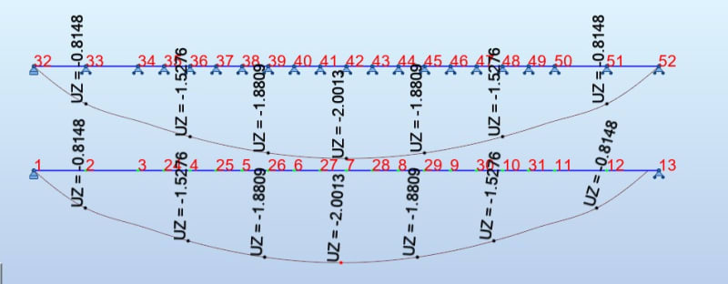
The other way to get the same results rather than figure out springs or applied loads at the panel points is to enforce the same displacements at your rollers:

Random model with the joist as a whole and then top chord only with enforced displacements:
Screenshot_2024-09-09_114314_gw0mz3.jpg


Moment plot of just the top chord and top chord "beam":
Screenshot_2024-09-09_115129_oiyfej.jpg


consistent vertical deltas:
note the graphic only displays the values for some nodes, you will need to enforce the same displacement at each node to get consistent results.
Screenshot_2024-09-09_114905_zqwdfc.jpg


Virtual 1kip load at the third vertical:
Note only the loaded vertical has axial load all other verticals are more or less 0 force members and therefore contribute little to no work to the system so their stiffness is almost irrelevant.
Screenshot_2024-09-09_114749_qnmvvj.jpg
 
Status
Not open for further replies.
Back
Top