Eng-Tips is the largest engineering community on the Internet

Intelligent Work Forums for Engineering Professionals

skewed slots in AC generator´s stator 2

Status
Not open for further replies.

petronila

Electrical
Jul 28, 2005
491
0
0
US
Dear all,

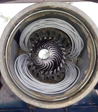
It is well known the skewed rotor bars in induction motors are used for avoiding CUSP, cogging and noise in three-phase induction motors. However, there is also the possibility of skewed slots in the stator. One of my collegues came to me looking for explantions of skewd slots in a 4160 V 5 MVA 4 Pole Synchronous AC Generator.

Does anyone knows for what were intended such skewed slots (all 60 slots are skewed)in the stator?

Thanks and Happy holidays!!

Petronila
 
Replies continue below

Recommended for you

It shouldn't make big difference on torque ripple or noise, whether the skewing is applied on the rotor or on the stator. Smaller induction machines typically have Aluminium die-cast rotor (and no radial cooling ducts), which makes it very easy to apply rotor skewing during the manufacturing (no extra manufacturing steps needed). Bigger induction machines (like the one you mentioned) typically have copper bars and rotor end-rings which are soldered together, plus rotor radial cooling ducts, which make it more complicated to apply rotor skewing during manufacturing. Probably it is easier to apply skewing on the stator side then. But I have seen both designs, I guess it depends on the manufacturer which they prefer (skewing on the rotor or on the stator). But the end results should be more or less the same.
 
If the designer of a machine needs additional circuit length in a smaller space,
skewed coils, or rotor bars, provide a means for gaining more circuit resistance.

John
 
fwiw I think along the same lines as jpts. It would logically be for the same purpose as in skewed induction motor rotor bars... to prevent various problems that arise from interaction of the rotor and stator spatial mmf harmonics. I guess those problems might include vibration and noise. But also there are torque anomalies that occur at various speeds during acceleration of an induction motor... similar might occur for acceleration of synchronous motor where the armortisseur windings are acting like a squirrel cage rotor during start.

I respect John's opinions on things like this, but I have a hard time imagining why increased resistance would be required... and if required wouldn't there be better alternate ways to achieve such a modest increase in resistance without the complexity of skewed stator slots / bars.

=====================================
(2B)+(2B)' ?
 
Thank you for the inputs.

I believe too the skewed slots in the stator are associated with harmonic prevention.

The coil pitch for a synchronous alternator should be a chord factor of 0.866 so the coil pitch needs to be 1-11. (4 Pole, 60 Slots).

If the alternator operates solo then the pitch is less critical, but if it is connected in parallel to the line or with other alternators, a 1-11 pitch will avoid the third harmonic.

This alternator had a 1-12 pitch. Then, I suspect the manufacturer skewed the coils for avoiding any kind of harmonic if the machine is paralleled.

Happy New Year!!

Petronila
 
Skewing of slots (stator or rotor) is primarily a means of reducing space harmonics associated with slot (or bar) passing frequencies. For larger machine designs - in particular synchronous machines with low pole count - skewing the stator slot is the preferred approach.

The skew does not have to be all one way, either. It could look like a herringbone pattern.

Converting energy to motion for more than half a century
 
The skewing of the rotor bars or stator-slots can be done in several ways. Even like this:

skew_jxllqs.jpg


The aim is to reduce step harmonics (order: k * slots +/- pole pairs; k is 1,2,3...) and thus prevent or reduce some side effects such as cogging, cusp and electrical noise, as these phenomena cannot be sufficiently reduced by any winding intervention (the pitch, connection, grouping, parallel paths, etc.).
Changing the pitch from 1-11 to 1-12 alone, can reduce the overall content of harmful harmonics but cannot reduce step-harmonics.
The harmonic content of equivalent winding (30 slots, 2 poles) for pitch 1-11 and 1-12 is shown below.

1-11_ztnhze.png


1-12_stjont.png


More at: [URL unfurl="true"]https://winding.wixsite.com/design/winding-analysis[/url]
 
Status
Not open for further replies.
Back
Top