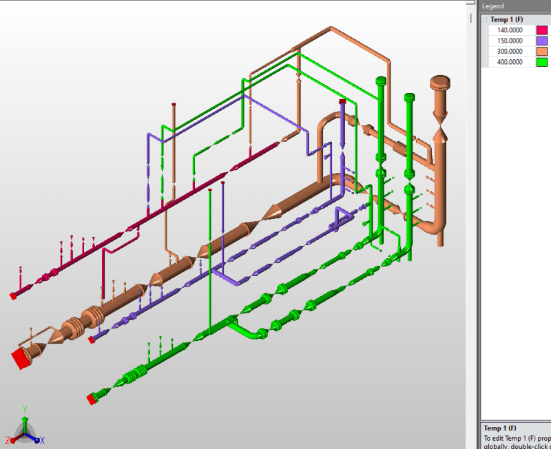
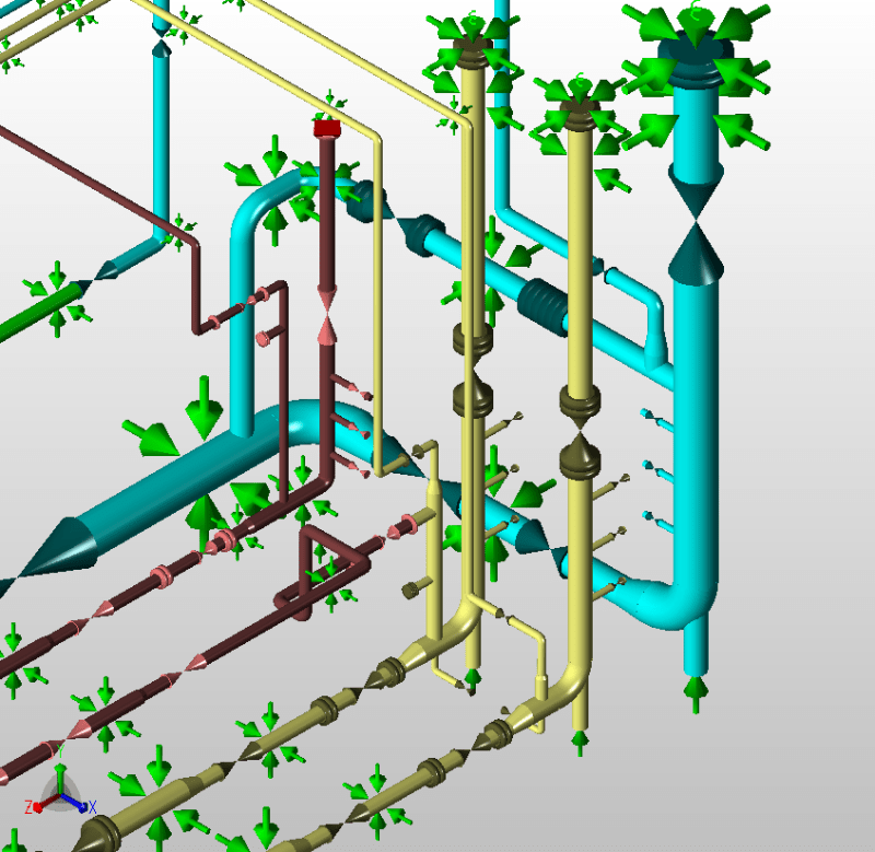
Hi all, this is my first post on here. I am doing stress analysis on a piping skid we designed containing various 6"-.75" pipes ranging from ambient (70F) up to 400F as a design temp. I've got the skid piping all modeled up in CAESAR II with the appropriate conditions aside from the boundaries. The skid is meant to be verified for general use so as to be reproducible. This means seismic and wind loads are not taken into account for this analysis; though, it should be noted that the piping has significant lateral restraint.
My uncertainty comes from how to treat the piping connections/tie points to other (not yet designed) piping. Typically in a stress analysis I would model all the way to some equipment and use an anchor at the nozzle node to determine the maximum loads on the equipment and see if they are under allowable loads (vendor/code specified.) In this case, I have assumed as many anchors as possible, starting with all inlet tie points. Our current piping configuration fails to keep expansion stresses under allowables with every inlet and outlet tie point anchored. I know that there is still some room between my mega-conservative model and reality that I can adjust to get an acceptable piping layout that passes stress checks, just not exactly sure what's right. Here is my best guess:
All of the skid will be connected to other piping which should have some inherent flexibility. Much like allowing for some nozzle flexibility to make a pressure vessel connection model a bit less conservative, I have reduced the anchor on some problematic outlets to the following restraints:
The axial restraint with stiffness needs some further clarification. Firstly, the outlet lines have an issue with compressing the vertical run underneath when the tie-point is anchored, since most of them have a sliding dummy leg support directly underneath at the bottom of the skid which offers no Y gap or flexibility. I have noted the free expansion by not anchoring the outlet tie-point, but see little use in this info other than that I know the actual displacement of these tie points will be somewhere in the middle of this and zero. I am treating this support stiffness for each tie-point as an independent variable and increasing its value right up until the piping fails the expansion stress check. At this point, the maximum allowable stiffness, and corresponding tie-point displacements/reactions are recorded.
It's almost as if I can see the skid connections being treated as an anchor in someone else's analysis, whenever the rest of the piping is dreamt up. In that case, the skid almost becomes a piece of equipment with its own "allowable nozzle loads", which helps to show my thought process on providing the client with some sort of allowable. That is the best I can think of, and I would be happy to hear suggestions on modeling something like this. Please do chime in on the tie-point anchor assumption itself and whether it is inherently always conservative as well. Surely a piping redesign is not out of the question, but undesirable.
My uncertainty comes from how to treat the piping connections/tie points to other (not yet designed) piping. Typically in a stress analysis I would model all the way to some equipment and use an anchor at the nozzle node to determine the maximum loads on the equipment and see if they are under allowable loads (vendor/code specified.) In this case, I have assumed as many anchors as possible, starting with all inlet tie points. Our current piping configuration fails to keep expansion stresses under allowables with every inlet and outlet tie point anchored. I know that there is still some room between my mega-conservative model and reality that I can adjust to get an acceptable piping layout that passes stress checks, just not exactly sure what's right. Here is my best guess:
All of the skid will be connected to other piping which should have some inherent flexibility. Much like allowing for some nozzle flexibility to make a pressure vessel connection model a bit less conservative, I have reduced the anchor on some problematic outlets to the following restraints:
-2 rotational restraints which lock the pipes alignment at the tie point node (for an outlet with +Y flow -> RX and RZ)
-Justification: The outlets are all vertical (Y-direction) with nearby guides so these reaction moments end up small.
-1 restraint along the pipe axis (for an outlet with +Y flow -> -Y)-Justification: I use this restraint to adjust the stiffness of the piping connection. While I do not know the direction of the force that additional piping will exert on the skid piping,
the direction which causes overstress on the skid is clear. The force is also likely to be -Y since all outlet tie points are vertical lines exiting the top of the skid.
the direction which causes overstress on the skid is clear. The force is also likely to be -Y since all outlet tie points are vertical lines exiting the top of the skid.
The axial restraint with stiffness needs some further clarification. Firstly, the outlet lines have an issue with compressing the vertical run underneath when the tie-point is anchored, since most of them have a sliding dummy leg support directly underneath at the bottom of the skid which offers no Y gap or flexibility. I have noted the free expansion by not anchoring the outlet tie-point, but see little use in this info other than that I know the actual displacement of these tie points will be somewhere in the middle of this and zero. I am treating this support stiffness for each tie-point as an independent variable and increasing its value right up until the piping fails the expansion stress check. At this point, the maximum allowable stiffness, and corresponding tie-point displacements/reactions are recorded.
It's almost as if I can see the skid connections being treated as an anchor in someone else's analysis, whenever the rest of the piping is dreamt up. In that case, the skid almost becomes a piece of equipment with its own "allowable nozzle loads", which helps to show my thought process on providing the client with some sort of allowable. That is the best I can think of, and I would be happy to hear suggestions on modeling something like this. Please do chime in on the tie-point anchor assumption itself and whether it is inherently always conservative as well. Surely a piping redesign is not out of the question, but undesirable.


