Continue to Site

Eng-Tips is the largest engineering community on the Internet

Intelligent Work Forums for Engineering Professionals

  • Congratulations KootK on being selected by the Eng-Tips community for having the most helpful posts in the forums last week. Way to Go!

Skin shear re-distribution

jpaero

Aerospace
Dec 14, 2007
24
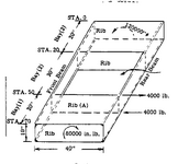
I have a structure similar to the one shown below. The structure was originally analyzed using FEA with Rib(A) present. Due to some issue, we need to ignore the presence of Rib (A). We are not in a position to re-run the FEM. We have the panel shear flows for each of the panels based on the original FEA. Since the rib became ineffective, the panel dimensions now change from 20" x 40" (Bay 1) and 30" x 40" (Bay 2) to being 50" x 40" (Bay 1+2). Each panel had shear flows q1, q2 and q3 based on the original FEA. I am unable to clear the combined panel for the max. shear when checking for shear buckling and I am looking for ways to remove conservatism. Can I assume the effective shear in the combined panel 1 & 2 to be (q1 x 20" + q2 x 30")/(20"+30")? I have seen this kind of averaging being done for panels along a cross-section but not so sure if I can do it along a span.

Also if possible, provide references for your answers.
1731117302710.png
 
Replies continue below

Recommended for you

I don’t see how averaging the loads, even if justified which I don’t think it can be, could possibly show the larger panel good. The buckling loads, both in shear and compression, will be lower than that of the individual smaller panels.

For more detailed help, provide
The buckling loads of Bay 1, Bay 2 and Bay 1+2
The applied loads in Bay 1 and Bay 2

Im assuming there are no stiffeners on the skin panels between the spar beams.
Thank you for the response. Yes, I totally understand that buckling loads of the combined panel will be lower than that of the individual smaller panels. These are not highly optimized structures and the applied loads are low enough for me to explore combining the panel.

If ok, I want to focus on the applied shear flow only and on the theoretical basis for allowing or not allowing the averaging of shear flows across the bay.
 
Make a FEM of a flat plate size of Bay 1+2 and do a study of buckling loads:
Uniform load.
Different ratios of Bay 1 to Bay 2 loads.
 
for my money, removing rib A removes the structure (the rib caps) distributing the rather large couple into the box, particularly in the compression side.

another approach, if this is the way you're going, might be to look into Bruhn's analysis for cut-outs, where he redistributes the shear in one panel, only for you it is a set of rib shears.

And here is where you say "the sketch is only similar to my case, and I don't have the loads shown". ok, sigh. If what you're saying is that you had a design with several bays, divided by ribs, and now you want to remove one rib (Y, oh Y ?) then averaging (or weighted average) may be a way to redistribute the loads. The rib cap is allowing the structure to have different shear flows in the two adjacent bays, removing the rib cap means the shear flow would be the same. But if this structure is so "suboptimal" (and that is not a slight at your structure) that you're not very concerned about the affect this change has on the allowable, then why not conservatively say "the larger of the two bays will be applied to both" ... surely conservative (and simple). Hopefully there are no loads introduced on this (missing) rib. Hopefully you'll test this before it goes into service.
 
Isn't this exactly what Bruhn Chapter A15 is for?
Do you have a copy of Bruhn's book, Analysis and Design of Flight Vehicle Structures?

If as you say, "We are not in a position to re-run the FEM" and maybe, I guess, not ever, then there's not much point in preserving or extending the FEM results. You no longer have this means to substantiate your structure, so instead of wasting more time adapting a quick fix until it works, just develop a new analysis without FEM to support the results that were previously determined.
 

Part and Inventory Search

Sponsor