Continue to Site

Eng-Tips is the largest engineering community on the Internet

Intelligent Work Forums for Engineering Professionals

  • Congratulations KootK on being selected by the Eng-Tips community for having the most helpful posts in the forums last week. Way to Go!

Skirt/Ring/Pedestal Support for Vertical Pressure Vessel

Status
Not open for further replies.

TylerM

Mechanical
Feb 16, 2017
32
I am hoping the experience on here could point me in the right direction or give me a design formula that I can use to check if the thickness of the skirt is large enough.

I have tried looking in numerous design handbooks and I can only find equations for a skirt that is welded to the straight flange of the head or directly where the tangent line is. The skirt I am working with is welded directly only to the head of the vessel, (I would guess the diameter of the skirt it to be around 80% of the diameter of the head) Is there any calculations that anyone knows of that could help me validate the design of the skirt?

Below is a picture of a pressure vessel similar to the one I’m working with.
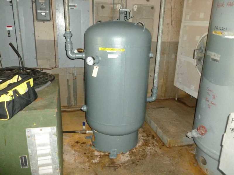
P1010058_lnfclc.jpg


Thank you for all of your help,
Tyler
 
Replies continue below

Recommended for you

MFJewell,

Thank you for your input, I am looking into Roark's right now. my main concern on this design is if the skirt is a thin wall and the head is also a thin wall, (and assuming relatively heavy commodity) will the head of the pressure vessel have be stressed extremely high where it contacts the skirt.

With a lot of force pressing down, the skirt almost acts like a knife cutting into the head. (Leading to failure of the pressure vessel)

Thoughts?
 
For the bending case only, try treating the head as an equivalent flat plate loaded with uniform load on one side, circular line load on the other side. That case is covered by Roark's, should require the superposition of two of the other load cases.
If he included similar loading for spheres or cones, that would get you a little closer.
 
I would wonder if localized loadings on the head could be evaluated by performing a WRC-107/537 evaluation. Your supported weight is an axial load that's being applied to the head by the support. Any distortion of the skirt could be factored in as additional applied moment. It's not necessarily spherical although it's possibly a roughly approximate geometry. It won't give an exact idea of the localized stresses although it could be a starting point. I'll leave further comments to more experienced people on this one.

Thanks,
Ehzin
 
I would bet the ratio of skirt size to crown radius of the head is out of the range of the WRC tables.
 
I wouldn't recommend foregoing the evaluation you already intend to do but I'm curious if an issue should be expected. With the picture you posted I'm imagining something of a similar scale but I suspect that's not the case. In addition to any analysis, you could also have the bottom head with a slightly increased thickness along with the skirt to distribute that point load you're worried about some. Pressure, fluid density, height, etc... would make a big impact if taking this approach would help.

And good point JStephen, kind of moves out of typical "nozzle" territory.

Thanks,
Ehzin
 
Tray to avoid this design: impossible inspection (visual, UT) inside the skirt. Use 3 legs

Regards

r6155
 
Status
Not open for further replies.

Part and Inventory Search

Sponsor