Eng-Tips is the largest engineering community on the Internet

Intelligent Work Forums for Engineering Professionals

  • Congratulations waross on being selected by the Tek-Tips community for having the most helpful posts in the forums last week. Way to Go!

Slab control joint on expansive site - greased or not greased 1

Status
Not open for further replies.

Euler07

Structural
May 7, 2023
53
0
0
AU
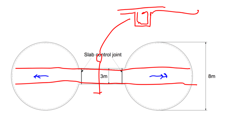
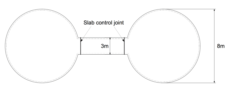
Hey all. We have a building that is being built on an expansive clay site. It is built using shotcrete concrete domes connected by a domed hallway. The slab is polished concrete so is highly susceptible to shrinkage cracking at the hallway. As a result, I am wanting to place control joints in the hallway slab at the locations shown in the image (dashed lines are walls of the concrete domes above).

I realise that dowels through slab control joints are best using a non-bonded dowel (such as greased or sleeved etc). However, since this is a reactive site and the concrete dome shell is above, I are trying to avoid any hinge action at the joint and would want full moment transfer. Therefore, I was thinking of using dowels that have full development on each side (eg. non-bonded with 500mm lap each side to slab reo). Would this at all reduce the plastic shrinkage cracking in the slab, or do you think that non-bonded dowels are the only way to go?

Thanks
Untitled_2_gtq2ee.png
 
Replies continue below

Recommended for you

So based on your question, you are trying to maintain a full dome-to-dome rigidity where the circular domes meet the hallway dome, correct?

The idea of a control joint is to induce a crack along a straight "joint" that you dictate - which is an attempt then to avoid random, irregular cracks elsewhere.
If you de-bond any reinforcement that is extending through this induced straight-line crack, then you defeat the ability to have a rigid moment capable intersection I would think.

For expansive clay sites I would think that two large masses tied together with a narrow hallway like this would want to be separated with expansion joints - allowing each of the three sections to move somewhat unhindered as the clay will move up and down in all sorts of combinations.

 
Just to clarify, the goal is to reduce shrinkage cracking in the polished concrete slab. But at the same time keeping the concrete dome (including the dome-to-slab starter bars) as a complete structure since the dome design and shape requires it to be a continuous structure.

What do you think is the main cause of cracking in polished concrete slabs? Is it the initial plastic shrinkage cracking or long term shrinkage cracking? My thought was that by having 2 separate pours (but making the reinforcement bonded and lapped each side of the joint) it would reduce plastic shrinkage cracking since this occurs prior to reinforcement bonding? (but would have no affect on long term shrinkage cracking) Is this correct? Or perhaps it is better to keep the slab as one continuous piece and place saw joint to control the cracking.

Also, I am placing continuous slab beams to try and limit differential movement between the two domes.

 
Expansive clays are sort of an irresistible force.
Large bodies like your big domes are going to move, a few slab beams will only make it mad.


Moment connections that allow translation are very difficult to accomplish. That type of connection (for that matter, any full moment connection) large enough to provide moment restraint to a structure of that size would be huge and expensive. I don't think it's a good idea to attempt to provide moment restraint between the domes. You're going to be much better off to design and detail the 3 pieces to be independently stable and linked by non-bonded dowels all around the connections - walls and roof, too, not just the slab, at the locations you've marked.

 
Thanks JAE. I was thinking that fully integrated footing/slab/dome would be a very stiff structure and that the structure would rise and fall together. Also, having movement in a joint in the dome would be a very bad look. I guess it's either movement in a joint or risk of cracking [neutral]
 
Potentially stupid idea but maybe support the edges of the domes/walls on the beams to allow them to be continuous + sit the slab on top the beams and allow it to slip? Seems like trying to have your cake and eat it too of one half (the slab) needs control joints and the other half cant (walls/beams).

I don't think you're in for a fun time trying to get anything 20m long to not crack on expansive soils however, main problem is the domes not being separated imo

----------------------------------------------------------------------

Why yes, I do in fact have no idea what I'm talking about
 
Another thought. In all my years of design on expansive clay, the most positive thing to do for major structures was always to support the structures on drilled/belled piers and perimeter grade beams separated from the soils with void forms and fill retainers.

Basically creating a spanning concrete foundation beam (on piers) with a 6 to 8 inch void below the beams.

The fill retainers are typically 1 1/2" thick precast concrete planks - say 18" wide x whatever length manageable - leaning on each side of the grade beam to keep adjacent earth from filling in the voids over time.

The piers are typically reinforced with 0.75% vertical reinforcement +/- and belled to help hold down any friction uplift forces by the clay on the piers.

For a large domed structure like this and with expansive clays, that would be to the way to go to ensure minimal movement.

 
Thanks JAE. I'm in Australia so it's quite normal to design for expansive clays here. We generally avoid piers since, as you mentioned earlier, the force from the expansion of clay is quite large and not feasible to resist using piers. We generally go for a grid system of slab beams with the goal not to necessarily prevent global movement, but to prevent differential movement by having the whole building rise and fall together. But I think your system would work well for large commercial buildings; although in this case I wouldn't feel comfortable supporting a concrete dome on isolated piers where any independent movement of a pier could cause issues. I'll keep your system in mind for future projects though.
 
Euler07,

I'm in Australia as well, and the system proposed by JAE is common in Australia. Perhaps not for houses. The piers go down beyond the swelling zone. Just columns in effect.
 
The first thought that came to mind to me was piles as well. We have high plastic clays and suspend all sorts of buildings on piles. This looks expensive and I would not mess around.
 
I think you need to decide if you want the structure to be completely rigid, or if you want to allow for some movement.

If the dowels are greased, then it's an expansion joint in my book.

If the dowels are not greased, or the typical reinforcement is continuous across the joint, then it is either a construction joint; or a control joint. Many engineers will reduce the reinforcement by 50% at a control joint to intentionally create a weak spot.

Just looking at the geometry and relative sizes of your structure, I like the idea of an expansion joint. Your structure is shaped like a weightlifter's dumbbell with large masses connected by a small mass. The inner connecting element will not be anywhere near as stiff as the outer domes. If either of the domes want to move, then you will likely crack the connecting element.

Put me down for expansion joints.
 
Put me down for piles as my first choice. I'm on the same muck formation as Brad805.

That said, I did a major university expansion using the grade beam method that OP described. That was for a more traditional building that was rectangular in plan with a 2.0+/- aspect ratio in plan.

My fear with using the grade beam strategy here is related to JoelTXCive's concern for the unique shape of this barbell thing in plan. You probably could run a stiff grade beam end to end that would iron out the differential movement end to end. But, then, the bells on the barbell would tend to twist as shown with the blue moments in the sketch below. Gross. To iron that out, you almost need to use a giant box beam for your grade beam in order to resist the twisting tendency with torsional beam stiffness. And I'd have to think such a strategy would be too costly to represent a practical solution.

C01_nyt4lk.png
C01_nyt4lk.png
 
JAE said:
The fill retainers are typically 1 1/2" thick precast concrete planks - say 18" wide x whatever length manageable - leaning on each side of the grade beam to keep adjacent earth from filling in the voids over time.

Well damn... I've always worried about the earth filling in the void and have never even heard of "fill retainers".

In my market, we specify "frost cushion" which is supposed to be permanent (questionable) and squishy enough to not resist upwards movement of the clay. It's then a battle to get contractors to actually use this stuff instead of void form which disappears and surely does let the earth fill the void in the absence of fill retainers.

@Brad805: what are you seeing in this regard?
 
Euler07 said:
the force from the expansion of clay is quite large and not feasible to resist using piers
That's simply not true. There are vast numbers of buildings supported on piers in highly expansive clay areas that resist uplift quite well via belled bottoms and extra reinforcement to allow for reduced uplift that only can occur via skin friction. As hokie66 says, it's quite common in Australia as well. And as Brad805 states, if your domed structure is an expensive, significant undertaking, I wouldn't mess around with a stiffened slab system that flexes back and forth - you'd end up with cracks everywhere with a stiff/rigid dome system like that despite your attempt to minimize differential movement.

Euler07 said:
...I wouldn't feel comfortable supporting a concrete dome on isolated piers where any independent movement of a pier could cause issues.
My view is that a drilled/underreamed pier system is much more stiff and stable than a stiffened slab system. Maybe by orders as much as 10:1 to 50:1 so I'm not sure why you think a few slab beams are going to keep the base from becoming irregularly warped.

 
Here's a rough sketch of the idea of using fill retainers to separate grade beams (spanning from pier to pier) from expansive clay soils below.
These would usually be about 1 1/2" thick reinforced with a welded wire mesh - usually simply cast on a 4' x 8' sheet of plywood on site using 2x4's as side forms:

Fill_Retainer_hbntzk.jpg
 
Status
Not open for further replies.
Back
Top