Continue to Site

Eng-Tips is the largest engineering community on the Internet

Intelligent Work Forums for Engineering Professionals

  • Congratulations KootK on being selected by the Eng-Tips community for having the most helpful posts in the forums last week. Way to Go!

Slab Corbel Design Question

Status
Not open for further replies.

atef81

Structural
Jan 7, 2010
12
Hi,

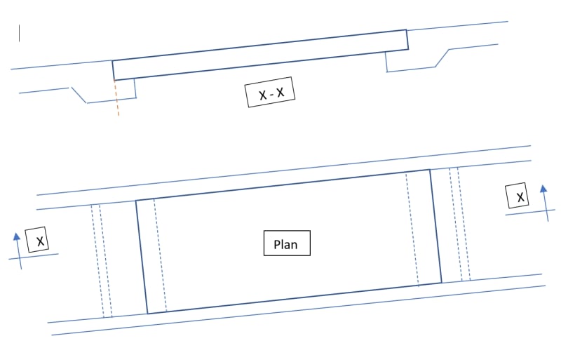
I am tasked to design a ramp in a building. The ramp is supported by slabs at either end via corbels.
The slabs are supported by walls at either sides. So the corbel is spanning between walls.

I modeled the ramp using Inducta SLB Software, with line supports at the corbel locations to obtain reactions per m of the corbel.

My questions is:

What is the best way to design the corbels?
Do I get the reaction and check the shear capacity of the section under the ramp (denoted in dashed orange line in my sketch). Then I check it as a simply supported beam that spans between the walls?

I checked many references and software (e.g. Tekla Tedds), they focus on corbels on columns using strut and tie method, but I could not find references to slab corbels.

Thank you very much.
corbel_2_qxz9od.jpg
 
Replies continue below

Recommended for you

The design approach stated by you is fine - corbel beam on each end to support loads from the ramp.

My question is what is the purpose of the removable slab?
 
I've encountered this in a couple of places.

1) I once investigated a failure of this condition on a bridge project. Design and detailing errors were the culprit. Do exercise some care with this, especially if you'll be supporting vehicular traffic.

2) I design a lot of continuous ledges similar to this in the precast world where such ledges are a part of inverted tee beams supporting hollow core slabs.

Here's what I can tell you that, i hope, will be useful to you:

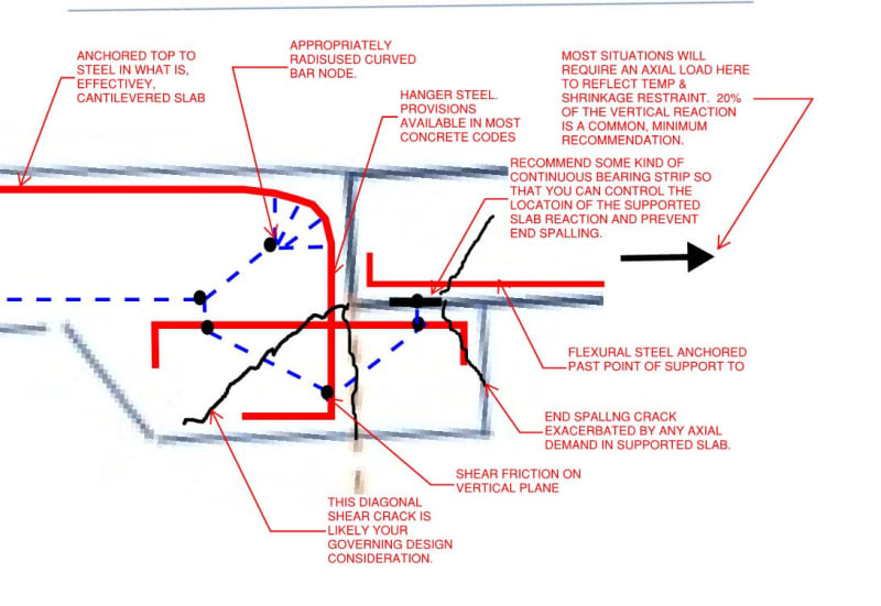
3) See the sketch below for a summary of what I consider to be the most salient design issues. Note that I have not shown every piece of rebar that I would include in the detailing but, rather, only those that I consider most important to highlighting the design issues inherent with this.

4) This is a bit less critical than normal corbel design where the corbel is a non-continuous, concentrated element. Concrete stresses tend to be much lower in proportion to the cross sectional properties of the corbel.

5) To my knowledge, none of the North American codes deal with linear corbel design directly. The Precast Concrete Institute has some related literature. I believe that the British standard treats a similar condition where the ledge is referred to as a "nib".

6) While a strut and tie analysis may not be necessary for the design of such an element, I feel that it's almost impossible to properly proportion and detail this condition without having at least a picture in on'es mind of what the strut and tie model might be if the design were undertaken using that method. The sketch below illustrates how I see things in this regard.
C01_wfdf7j.jpg
 
Can you use an angle at the nosing with rebar welded to it? I used to use Elastometal type GNN teflon bearings way back... there maybe something similar... also 20% seems high for a horizontal component.

Dik
 
Hi Dik,

20% is a reasonable assumption. AS 3600 requires a a minimum value of 20% of the vertical force when designing corbels or nibs
 
I usually do these with PTFE bearings... haven't done one for a bit... just seems a tad high... but, OK.

Dik
 
Tension on the upper corbel, compression/bearing on the lower corbel, which may require damper there to lessen the impact.
 
Following on from the concept kootk noted, if you look at page 98 of this document it has a similar method that is used to size hollowcore support ledges on beams which I'm sure can be adapted to the similar scenario you have.

Note that most bearing strips will have higher friction than 0.2 between the concrete and the strip. The above document goes as far as saying that it should be designed for 0.7 times the support reaction.

In your case the infill slab wants to naturally slide downhill. You may want a central dowel or vertical pin on the downhill side to prevent the but still allow slab to pivot (presumably to take up some movement parallel and orthogonal to the ramp due to seismic?)
 
Hi All,
Thank you very much for your much valuable help. I am very new to the forum and did not know how to mention each one by their name to thank each one individually. Very much appreciated.
 
Status
Not open for further replies.

Part and Inventory Search

Sponsor