Continue to Site

Eng-Tips is the largest engineering community on the Internet

Intelligent Work Forums for Engineering Professionals

  • Congratulations KootK on being selected by the Eng-Tips community for having the most helpful posts in the forums last week. Way to Go!

Slender Column check (varying column dimension) 1

Status
Not open for further replies.

BulbTheBuilder

Structural
Aug 18, 2021
307
I am running an analysis and design check on an existing column. The flat slab at the mezzanine floor is to demolished which will result in about 30' long column. The column size above the mezzanine floor varies from the size below. In this scenario, how do I check slenderness for this column(non-braced)?

Do I use an averaged "r" to check the slenderness effect? Does same applies to "I[sub]g[/sub]"? How do I effectively account for my stability properties "Q" and "Pc"? Is it possible for the upper column to buckle without the lower one? What the best way to approach this problem?

The building is a hotel and the column happens to be exterior so it has low-gravity load and lateral load (wind on the column). I have attached a sketch of the column
 
 https://files.engineering.com/getfile.aspx?folder=f1539e74-696d-4e18-bd37-9d547e889823&file=COL_LY.pdf
Replies continue below

Recommended for you

Do not mistake that for a single column. You have a column on the upper floor and a column on the lower floor. Check them each over their respective unbraced lengths, with their respective loads and section properties.

 
Won't the columns be a single column after the flat slab has been demolished?
 
From a buckling perspective, that two story column won't be much better than it would be if it was the upper cross section all of the way down. So that's how I'd be inclined to check this unless you're utterly desperate for more capacity. The averaging business isn't appropriate here in my opinion.

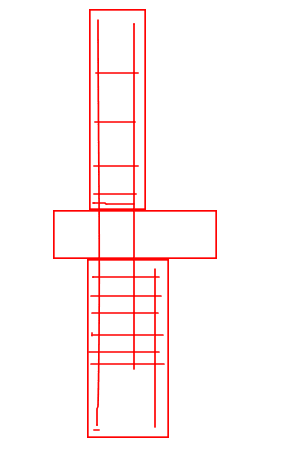
dL is absolutely correct in that there needs to be a moment connection between the upper and lower columns for this to work. That said, conventional rebar detailing for such a condition will normally provide a pretty decent moment connection there. Got any info about the rebar at the joint?
 
Yes, sorry I missed that part of it. Still you don't want to average anything here I don't think, the top could buckle before the bottom or they could both buckle together. Perhaps you could still look at each segment separately and come up with a representative K factor.

**Edit Also agreeing with KootK that assuming the upper section throughout is a good way to start and conservative.
 
In skilled hands, these joints usually look something like this.

C01_edv1ge.png
 
Thank you all for your comments. From the copy of the drawings I have, the 24x24 col is reinforced with 8-#9 and the 12x30 col is reinforced with 8-#10.

[edit]: I am going to be conservative and run the 12x30col down for my analysis. I can easily do the analysis for that. If the column fails under slenderness then I'll proceed to check with a bigger size and recommend wrapping the column
 
Couldn't he use the sum of the rotational stiffness to come up with a k factor at the moment connection between the top and the bottom.

Then use KL/r for each segment and check each segment as single columns?

Its doubtful this would give much of an increase over what KootK already has mentioned but I think this is the correct way to apply the effective length method in this scenario.

 
Bulb_the_Builder (great name by the way!) -

For certain I know the "equivalent" slenderness will be lower than the skinny column using full length and higher than the fat portion of the column using full length. So, we've got an upper bound and a lower bound to our problem. Like KootK, I suspect it will probably behave closer to the skinny than fat portion.

Now, if we wanted to be "exact" with our investigation, then we could use a method of calculating elastic buckling strength that AISC mentions in their design guide for tapered members. In that design guide, they talk about a technique called "Method of Successive Approximations" which can be used for calculating the elastic buckling load for a tapered or stepped column. There may even be an appendix dedicated to this technique. The reference is to and article by Timoshenko and Gere from 1961.

This method is really not all that complicated if you're using Excel. They've even got a worked example for a stepped column that you could follow. Once you find the elastic compressive strength, you could back out an "equivalent" slenderness ratio.

Note: Even this may not be 100% accurate because AISC is talking about pure elastic buckling and I believe ACI uses some fudge factors on their elastic buckling to account for an assumed level of cracking.


Thank you JoshPlumSE (Structural)!

I am supposed to deliver an update tomorrow (end of the day) so I don't think I will get enough time to read, understand and implement that approach (unfortunately, the industry has made things this way) . That being said, I will put it on my to-do list for the weekend so I can get better understanding of it. I really appreciate it.
 
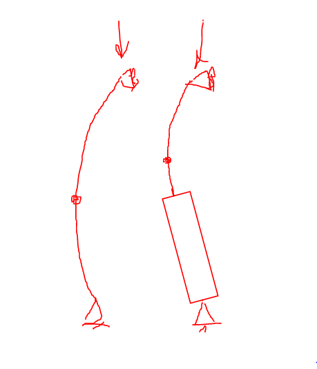
I could do fancier things than this but I likely won't. This is how I see it: the stiffer bottom bit just shifts the inflection point upwards a bit in a way that probably doesn't reduce K, or increase buckling capacity, all that much. To the extent that the bottom and top of this thing have any rotational restraint -- as I expect they would -- that will just make the difference even less.

C01_hwjzo2.png
 
KL = 2 X distance from the top down to the IP in both cases.
 
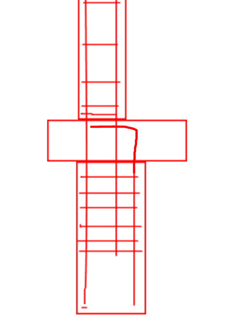
Hey KootK, this is a separate question, but don't you need L-shaped dowels between the slab and column? I always specify that because I think it's good as a failsafe for punching shear, though I've only met one other engineer (works in WSP) who specifically calls it out on plans. Every section I've seen doesn't have it. I even read the CRSI books and they don't have it.
 
MSL said:
...but don't you need L-shaped dowels between the slab and column?

That's a good detail mechanically. That said:

1) I don't feel that it is necessary so long as the offset lap splice in the low column is well detailed.

2) On larger column bars, the hooks can get ugly for congestion etc. Better if they're lapped with smaller hooked dowels.

3) Yes to some kind of punching shar improvement where the moment would be CCW in my sketch. That said, when I check these things, I just assume that both columns are the size of the smaller column for punching shear. That mechanism is stiff owing to the rather great clamping action engaged. I'm luke warm on a dowel's ability to hold down a slab in a way that would improve punching shear meaningfully. This is similar to how I find punching shear moment transfer at roof conditions (and footings) a bit questionable sometimes.

 
I assume that this is what we're talking about, perhaps with the dowel turned outward. I've certainly seen that in some firm's standards.

C01_av87hp.png
 
@KootK Got it. Yeah, congestion is always a concern at columns, especially for taller buildings. Too much and the concrete won't flow, and you got much bigger problems.

About your concern regarding a dowel's ability to hold punching shar, I read a case study of a garage punching shear failure that killed a bunch of people. I can't remember the name offhand. Anyway, some parts of the slab didn't fail, and the only reason was dowels. The study had some pictures of a slab being cracked but still held up with literally two #4 dowels with a few inches of embedment. So that scared me into always using it. And yes, that's exactly what I meant.
 
I have seen some interesting comments that I'd need to look more into them. I really appreciate the comments. Thank you all
 
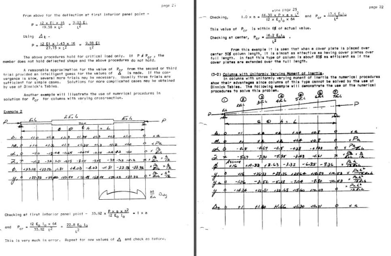
The article in Timoshenko and Gere referred to a method proposed by N.M. Newmark. Attached are two pages of notes taken by one of Newmark's students illustrating the method used for members with variable cross section.

In the present case, eccentricity of load on the lower column should be included. Buckling would tend to be toward the slab which was removed.

Capture_zytzv5.jpg


BA
 
You can check this in Vector2 if the simplified options do not work out as you want. There is a free version for this model size and complexity. It is not overly difficult to use. Video
 
Status
Not open for further replies.

Part and Inventory Search

Sponsor