Continue to Site

Eng-Tips is the largest engineering community on the Internet

Intelligent Work Forums for Engineering Professionals

  • Congratulations KootK on being selected by the Eng-Tips community for having the most helpful posts in the forums last week. Way to Go!

Slender Column check (varying column dimension) 1

Status
Not open for further replies.

BulbTheBuilder

Structural
Aug 18, 2021
307
I am running an analysis and design check on an existing column. The flat slab at the mezzanine floor is to demolished which will result in about 30' long column. The column size above the mezzanine floor varies from the size below. In this scenario, how do I check slenderness for this column(non-braced)?

Do I use an averaged "r" to check the slenderness effect? Does same applies to "I[sub]g[/sub]"? How do I effectively account for my stability properties "Q" and "Pc"? Is it possible for the upper column to buckle without the lower one? What the best way to approach this problem?

The building is a hotel and the column happens to be exterior so it has low-gravity load and lateral load (wind on the column). I have attached a sketch of the column
 
 https://files.engineering.com/getfile.aspx?folder=f1539e74-696d-4e18-bd37-9d547e889823&file=COL_LY.pdf
Replies continue below

Recommended for you

MSL said:
Anyway, some parts of the slab didn't fail, and the only reason was dowels. The study had some pictures of a slab being cracked but still held up with literally two #4 dowels with a few inches of embedment. So that scared me into always using it.

That sounds a lot like how integrity steel functions in new builds constructed modern codes.
 
Not sure if this has been addressed, but based on OP's sketch the column above is wider than the column below: (12"x30") vs (24"x24").
Hence the full compressive section cannot be realistically justified. I would be checking it for the overlapping region (12"x24") as a first pass instead.

With regards to the varying section I would be running a buckling analysis:
1) Whole length with the smaller section, get buckling load of F1
2) Whole length with both sections (and appropriate offsets), get buckling load F2

3) Check the the column with the smaller section for its entire length, but adjust its effective length factor such that the buckling load will = F2.


BulbTheBuilder said:
@BAretired (Structural): What's the name of the article?

Theory of Elasticity by Timoshenko and Gere, Article 2.15 The Determination of Critical Loads by Successive Approximations.

Also, all 25 pages of the Newmark notes are contained in SlideRuleEra's "contribution by others".

BA
 
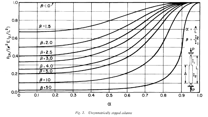
Sorry to be late to the party here... A slightly more production-appropriate way to account for additional buckling capacity in this case would be to use the nomographs in Dalal's 1969 paper "Some Non-Conventional Cases of Column Design". I've attached one below, although there are a few permutations depending on stepped section and loading configurations.

Dalal_Nomograph_se9w1v.png


----
just call me Lo.
 
How is the reinforcing developed in the middle? Simple compression splice?

-----*****-----
So strange to see the singularity approaching while the entire planet is rapidly turning into a hellscape. -John Coates

-Dik
 
Status
Not open for further replies.

Part and Inventory Search

Sponsor