Continue to Site

Eng-Tips is the largest engineering community on the Internet

Intelligent Work Forums for Engineering Professionals

  • Congratulations GregLocock on being selected by the Eng-Tips community for having the most helpful posts in the forums last week. Way to Go!

Slenderness Minor Axis Length

palk7 EIT

Structural
May 12, 2020
150
Hi,

These are roof beams, but on some loading cases (lateral) there are compression forces in these members. These members are fine for its major axis bending action and gravity deflection, however, because of the length and the minor axis (ry) value, the slenderness limit exceeds 200 and get a failure in the program (Staad).

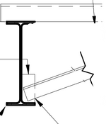
I have detail attached with L-angle braces from the W-beam going back to roof diaphragm at mid-spans and can even use a full depth stiffener there. Could these be counted to reduce the unbraced length in minor axis compression to half of the span to get the slenderness limit less than 200 or is there anything that you do to counteract similar situation.

Your thoughts are highly appreciated.

Thank you
 

Attachments

  • 2B.jpg
    2B.jpg
    37.1 KB · Views: 5
Replies continue below

Recommended for you

That's a pretty common approach and, in general, I don't feel that you need the stiffener. Or, at the least, not a full depth stiffener.

Your detail show the brace tying into the deck. I've never seen it done that way. Usually we tie into the top flange of a framing member like a joist or beam. More robust load transfer from the brace.
 
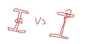
I think this also gets down to flexural buckling vs flexural torsional buckling (FTB).

I believe the roof deck would brace the beam in it's weak axis for flexural buckling. The roof deck does not provide adequate bracing for FTB. If the beam still fails in compression for FTB, then that kicker would be required to brace the beam midspan for FLB.

I suspect this (metal deck bracing ability) has been discussed on these forums in detail in the past, and my take on it may be different than the consensus.

For STAAD, I would put Ly = 1 ft , and Kx = 1.0 for no brace, or Kx = 0.5 for braced midspan.

As KootK noted, I have seen a small plate at the bottom flange to connect the brace to, and the brace would tie into another beam as he mentioned at the top flange with a similar small steel plate.

1736445980852.png


Another thing to consider, do you need to put the wind load into STAAD for the full load path? You could skip a few steps of the load path and put the loads on the left and right beams that act as drag struts or moment frames. You can calculate the diaphragm and chord force checks by hand if that is easier, while STAAD will design your actual moment frames/braced frames.
 
KootK:-I saw this on one of the office buildings where they had the L-angle brace onto the metal deck. In this case the adjacent steel (Open web steel joist) is 6' away from this, when I have the angle brace onto the OWSJ the angle comes out to 14 deg. approx. is that slope ok for a brace?

HDstructural:- can you help me why you would use Ly=1 ft in STAAD, doesnt that mean the minor axis is completely braced by the diaphragm? but however the angle brace is only at the mid-span of the member.


Thank you
 
-I saw this on one of the office buildings where they had the L-angle brace onto the metal deck.

Any chance that was a floor deck with concrete on top?

when I have the angle brace onto the OWSJ the angle comes out to 14 deg. approx. is that slope ok for a brace?

Not just ok, better. At least as far as expected structural performance goes. A stiff brace is an excellent brace.
 
The diaphragm is typically attached to the steel using a 36/4 pattern or something similar. This means the deck is fastened to the beam top flange at 12" o.c.

The beam is braced by the metal deck again weak axis buckling at 12" (1 ft) oc by the metal deck fasteners. The angle at the bottom flange is not needed to brace against weak axis flexural buckling since the metal deck is already doing it.

If your fasteners were spaced at 18" oc, you could use Ly = 1.5ft

The angle serves two purposes:
  1. It braces the bottom flange for lateral torsional buckling of a beam in bending. This is sometimes needed in design of roof beams with significant uplift as the bottom flange can go into compression. This may not be needed for your project.
  2. It braces against flexural torsional buckling in compression. To brace against FTB, both flanges needs to be braced. The angle at the bottom flange braces the bottom flange, while the metal deck braces the top flange. The brace location is where the top and bottom flange are both braced against FTB which is at the angle brace location.
 
Kootk:- that was hard to say I am not able to recall but I think there was one more floor above, so could be with concrete topping. But attached detail below where there is a continuous L-angle running across the OWSJ and bolted to top chords and deck and the brace gets attached here, is this a better detail?
 

Attachments

  • 33.jpg
    33.jpg
    413.6 KB · Views: 6
HD Structural:- Thats good to know I was using UNT & UNB for inputting the unbraced length for top and bottom extreme fiber in compression.
 
UNT and UNB are inputs that only impact the flexural capacity of the member. Kx, Ky, Kz, Lx, Ly, and Lz inputs only impact the compressive capacity of the member.

You typically need to input things twice (UNT = 1 ft, Ly = 1ft, UNB = 12 ft, Lx = 12 ft) so that STAAD applies the correct parameters to both axial design and flexural design.
 
is this a better detail?

Probably. The main concern with attaching to an untopped deck between deck supports is that the strength and stiffness of the deck is pretty paltry relative to the more serious framing. I've no idea if it would be good enough but I'd rather err on the side of being over braced than under.
 
Historically, it has been very common to treat such beams by simply taking the weak axis unbraced length as the distance between discrete braces that brace the cross section rotationally. This will typically provide a conservative -- but not overly conservative -- estimate of the torsional buckling strength which will normally govern.

In addition to its inherent reasonableness, this approach was chosen because torsional buckling checks can be pretty complex and often were not available in the common FEM programs. That, particularly given that the particular form of the torsional buckling is usually constrained axis torsional buckling wherein the beam buckles about the top flange rather than its own shear center. This results in an improvement in capacity.

This historical practice may be useful for you to know when reviewing other peoples work or the body of literature available on this stuff in the wild. If you've got software capable of fancier things... go nuts.

c01.JPG
 
HDStructural:- In STAAD could you do the DAM (Direct analysis method) check/ design the member strengths and then in the same model do regular analysis without DAM to check for the member deflections? without having to remove the DAM commands?
 
UNT and UNB are inputs that only impact the flexural capacity of the member. Kx, Ky, Kz, Lx, Ly, and Lz inputs only impact the compressive capacity of the member.

You typically need to input things twice (UNT = 1 ft, Ly = 1ft, UNB = 12 ft, Lx = 12 ft) so that STAAD applies the correct parameters to both axial design and flexural design.
Cantilever's need to be analyzed carefully, there are articles that provide K values for bending equations specifically for cantilevers. Just FYI to OP.
 
I usually manually check deflections in STAAD. So I am not 100% sure, but I think you can still input the DFF parameter with all of the other ones and it will check the deflections. I just don't know if it checks the LOAD LIST load combinations you use (which could be LRFD or ASD depending on your design method) or if STAAD knows to only check deflection against the serviceability envelope that you can set up.
 

Part and Inventory Search

Sponsor