Eng-Tips is the largest engineering community on the Internet

Intelligent Work Forums for Engineering Professionals

  • Congratulations waross on being selected by the Tek-Tips community for having the most helpful posts in the forums last week. Way to Go!

Sliding aircraft hangar doors - Pin connection replacement

Status
Not open for further replies.

LexW.

Structural
Nov 10, 2023
3
0
0
CA
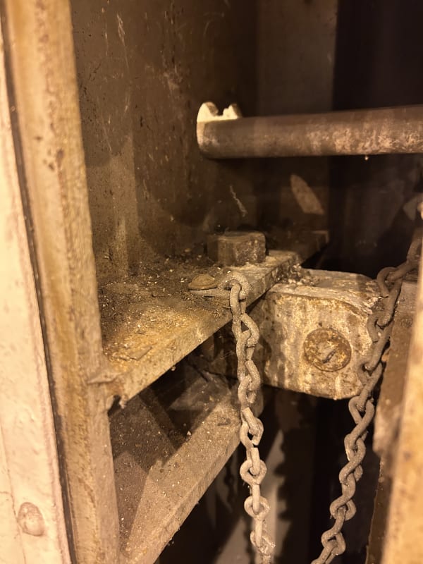
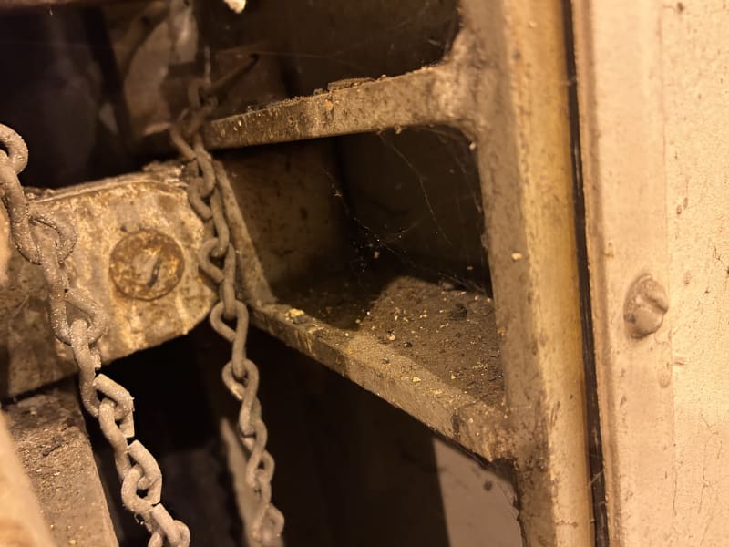
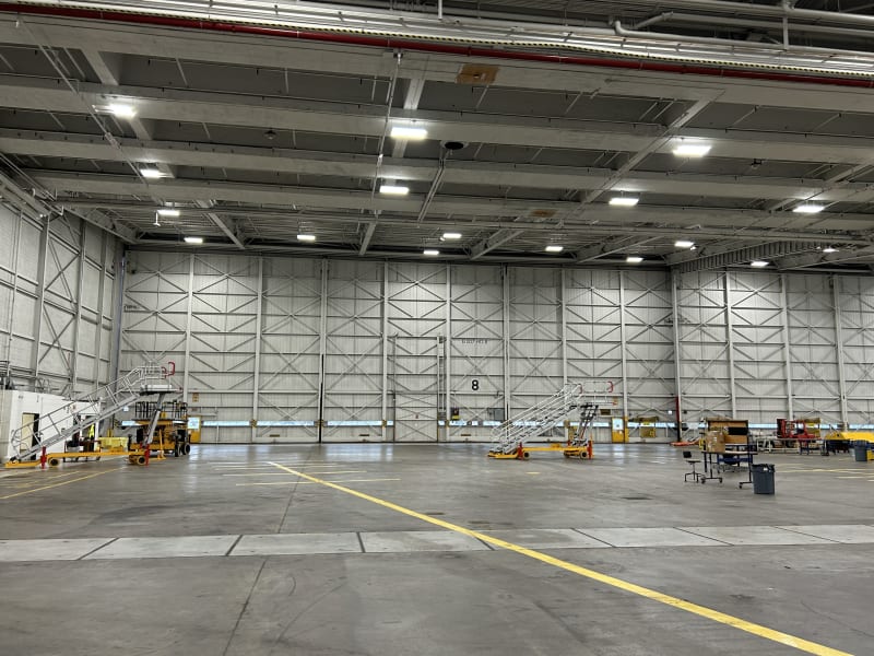
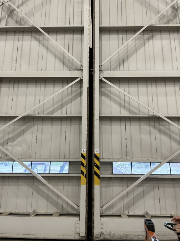
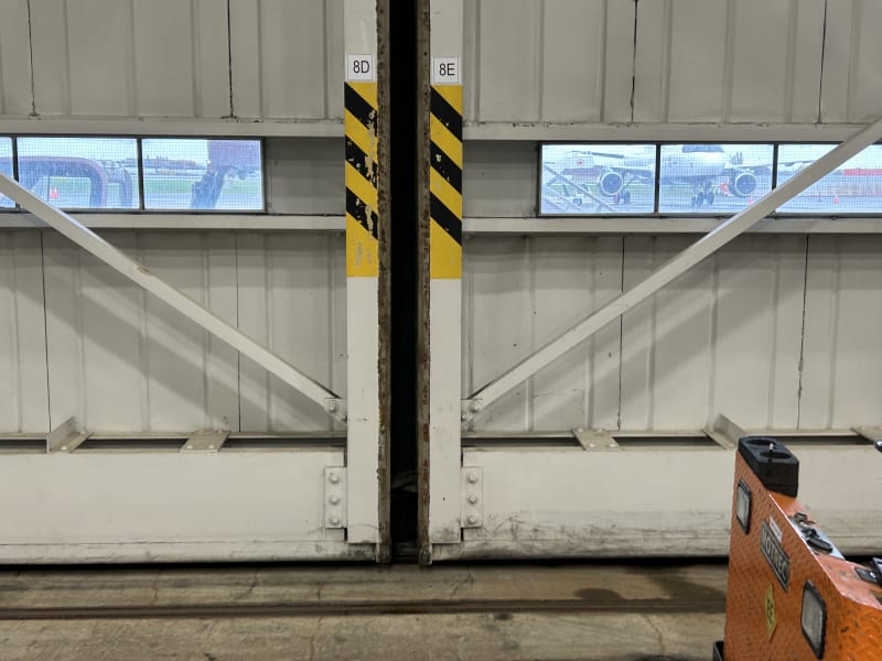
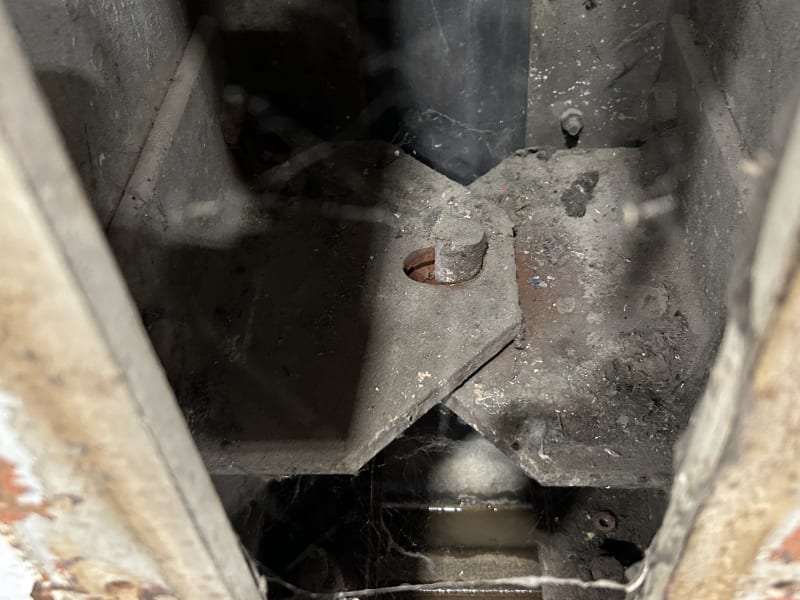
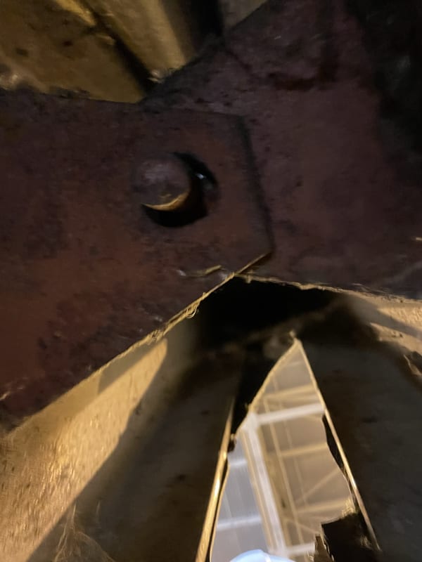
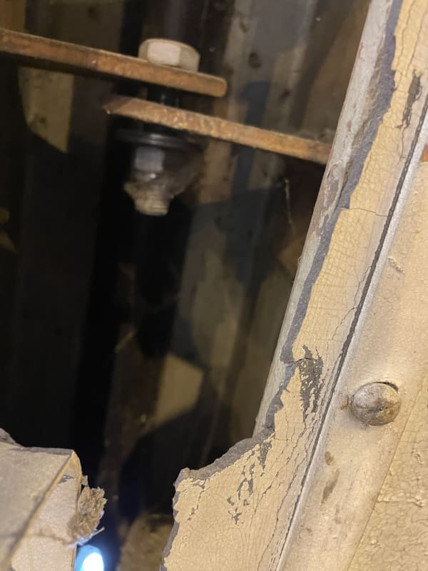
I have recently been assigned a project involving the design of new bottom pin connections for sliding aircraft doors to replace some of the existing ones that are old and damaged. The doors are 48m long and 16m high, with articulated joints located at 1/3 and 2/3 of their length. Each articulated joint comprises a bottom and top connection. The client specifically wants to change the bottom pin connections. The original ones consist of two L-shaped steel sections that are either bolted or welded to each side of the door structure, and a dowel in the middle slides through a slotted bolt hole in the top L (refer to below pictures for clarification).
IMG_4094_wjwgtr.jpg
IMG_4097_klsyeo.jpg
IMG_4098_fbhpw8.jpg
IMG_4099_rlcws7.jpg
IMG_4100_oi6de2.jpg


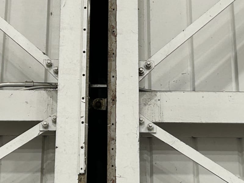
Initially, I thought these connections served to transfer transverse load from one panel to the other, and that the impact of force transfer was causing damage to the existing connections. However, my perspective changed after observing the door in operation. It appears that the load transfers through the top connection exclusively. The dowel of the bottom joint moves 1/2 inch parallel to the doors but does not transfer any load between the door panels (no contact between the two L sections).

The challenge I'm facing is understanding the purpose of these connections in order to design new ones. The damaged ones seem to have been installed in the years after the construction of the doors. The L sections on the "newer" connections lack slotted holes in the top angle, which may have caused the observed damage during maintenance when portions of the doors were lifted (refer to pictures for clarification).

IMG_1785_wvhusx.jpg
IMG_1786_pci8r0.jpg


If anyone has experience in designing aircraft hangar doors and can provide insight into the purpose of these connections, it would be greatly appreciated.

Thank you.
 
Replies continue below

Recommended for you

If the doors slide side-to-side, I'd say they transfer the load between doors. The L sections don't have to be in contact for that to happen. The pin has to be in contact with both of the L sections, and it is in the bottom right picture in your post.

If there isn't any load transferring, perhaps it's because it is damaged and the other constraints (top and bottom rails, for example) don't allow the door to rotate into an alignment that would load the good connection and the damaged connection equally. As a result, more load ends up in one connection, hastening complete system failure (aka: zipper).
 
phamENG said:
If the doors slide side-to-side, I'd say they transfer the load between doors. The L sections don't have to be in contact for that to happen. The pin has to be in contact with both of the L sections, and it is in the bottom right picture in your post.
Agreed. The Ls don't have to be in direct contact but the pin has to transfer the load. These doors slide in both directions so yes the pin is in contact if the door moves to the left in the picture you mention. That being, said I've watched the doors operate, the pins don't slide in the slot from one edge to the other to transfer the load. They maybe move 1/2 in in the slot without reaching the other side. Let's assume they did, wouldn't that back and forth impact of the pin on the bearing surface of the slot induce impact force?

phamEng said:
As a result, more load ends up in one connection, hastening complete system failure (aka: zipper).
The top connections are bulkier than the bottom ones and are in better condition.
IMG_4069_tp7q7w.jpg
IMG_4067_r5cqwf.jpg
 
I'd be willing to bet those holes were never meant to be much more than 1/16" larger than the pin. Look closely at your pictures. They're elongated. And not in a slotted hole style. More in an irregular, there's-material-built-up-at-the-bearing-edge sort of elongated. Hertz contact stresses are at it again!

Could there be an impact force? Sure. Maybe that's why the holes are elongated.

Maybe all the load is meant to go through the top one and the bottom are just to stabilize it? Don't know. You'd have to evaluate the top connection to see if it can handle it.
 
LexW.:
I’m not an airplane hanger sliding door expert, but here’s my take on the problem. The larger door panels are about 16m long, btwn. pinned vert. joints, and about 16m high from a strong horiz. spanning fl. level beam to a top horiz. spanning beam which includes/takes the opening and closing force transmission. The large top and bot. beams span vertically to carry gravity loadings and horiz. to pick up wind loads etc. The large door panels are about 52.5' sq., and they have two edge styles (cols., posts) and two interior styles, about equally spaced. The styles are numbered 8A, 8B, 8C, 8D, vert. pinned jnt., 8E, etc., per your photos, and there should be roller dollies under styles 8A, 8D & 8E, 8H & 8I, etc. to take door loads to a fl. track.

The actual door operating mechanism, a cable drum/winch system, which pulls the sliding doors open and closed, is up at the top of the door. So almost all of the force/load for this action, and btwn. the three large door panels, is taken by that more robust top pin connection. Obviously, the three plate (2 side pin pls. & a center pin pl.) , the pin in double shear, fairly tightly fitted connection, is a fairly strong connection to transmit these operating loads. Note that this pin axis is horiz., and perpendicular to the plane of the doors. This allows the large door panel to rotate a little about this pin axis as the roller dollies on a given panel, or btwn. two adjacent large panels moves up and down on the fl. track. The large panels are fairly stiff given all the framing, bracing and ext. sht. metal, so they tend to rotate as rigid panels. This shows up as the 1/2" of longitudinal pin movement you saw in the lower pin connection pls. The fl. track will have some levelness tolerance, but over time it settles a bit or moves with expansion and contraction, etc. And, you would have very large loads on these pinned joints if you did not allow the bot. pinned jnt. to move longitudinally some amount. Those bot. holes were probably punched as over sized slots (more than 1/16" clr.), maybe an elliptical shape. I wouldn’t expect much impact loading on this jnt., but more in the way of abrasion from repeated loading. The loose pin/bolt can’t transmit much load, but keeps the panels together at the bottom. Note that there is not much relative vert. movement at jnt. 8D-8E because of the tight upper pinned connection and the fact that the roller trolleys are near each other under this jnt.

I’d look for some sliding door drawings and maintenance info. from the hanger owner or the door manuf’er., and see what you can learn from them. I’d look for the best performing lower connection design, probably the manuf’ers. design, and replicate it. The repair design was probably not too well thought out. The 5th photo, the gray one, looks like the orig. design, an elliptical hole and the solid pin plug welded to the bot. pin pl. from below. A bigger dia. pin and thicker pin pls. wouldn’t hurt anything, but add wear surface. If you use a bolt, use a non-tightened lock nut, and large dia. heavy washers t&b.
 
dhengr, thank you for your detailed response. That's the conclusion I was heading towards as well. Unfortunately, the original drawings of the doors are no longer existant. I've been trying to find documentation from other manufacturers but they're very secretive.

PhamEng thank you for your reponse. If you look at the 5th picture I posted you can see that the elongated holes are punched that way. This is an original connection,
On newer Ls where slots weren't considered, yes the holes are elongated due to bearing failure. These doors are often lifted for maintenance therefore my theory is that they were damaged from the moment generated during the lifting process + the fact they were probably not engineered.
 
LexW. said:
The challenge I'm facing is understanding the purpose of these connections in order to design new ones.
...the fact they were probably not engineered.

Seems that way because this part of your question is not structural... it's addressed in the "Kinematics of Machines" branch of Mechanical Engineering.

Ask your question in the "Mechanical Engineering, General Discussion" forum. It will take more than a few photos, but with some effort on your part, you may gain insight into how the mechanism is supposed to function... allowing you design a replacement and maybe some appreciation of the capabilities of other engineering disciplines.

 
Hi Lex

the pin is to link multiple door sections together. each door section has 2 wheels and then the big slab section has 6 wheels or more.

The principle is like a train there the connection between wagons allows for vertical movement yet allows the wagon to pull without jerking.

normal it about be 3 plates about 1/2inch thick two on one door section about 50mm apart with an 1" shaft held tightly. The third would be between the two plates with a slight 1mm clearance hole on the pin.

this should allow 10mm up and down movement

like a train
 
Status
Not open for further replies.
Back
Top