Hello everyone,
I am currently working on a 3D FE model in ABAQUS, focusing on simulating thermal force resulting in a rail break which generates a gap in the rail.
Model description:
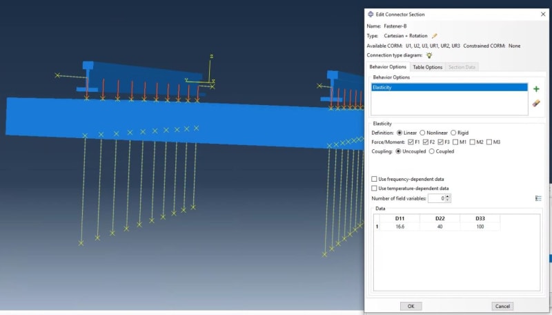
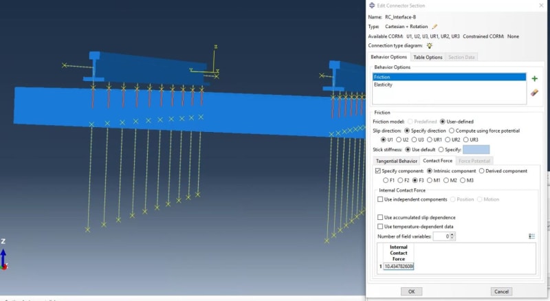
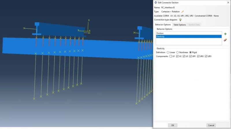
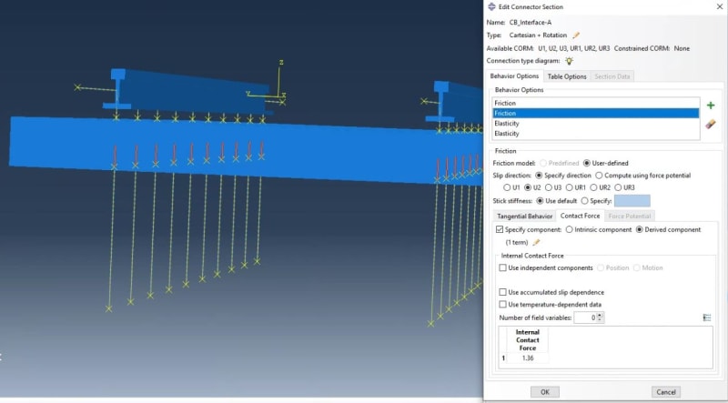
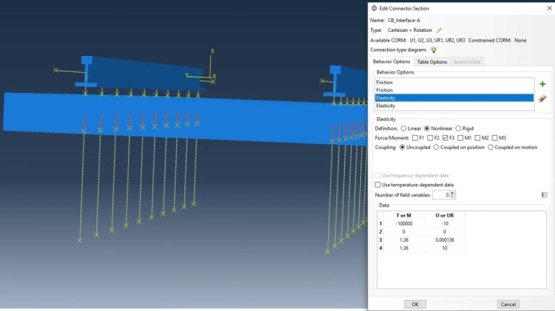
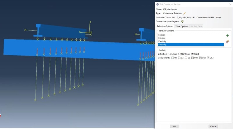
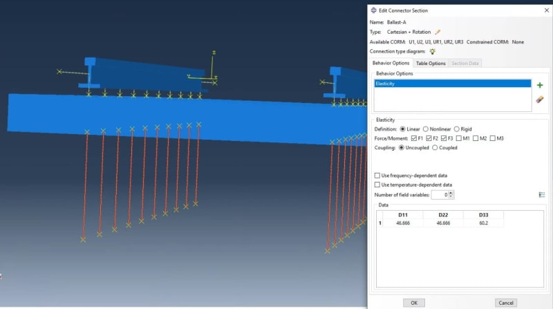
This model applies a compressive load in the longitudinal direction, aligned with the rail length, equivalent to the thermal force, causing rail displacement as a result of this loading. Friction-based components are used in series with elastic elements to define the rail-sleeper and sleeper-ballast interactions. Non-linear spring elements simulate the elastic properties of fasteners and ballast in the vertical, lateral, and longitudinal directions. Friction-based elements model the interaction between normal force and friction coefficient for each nodal degree of freedom, allowing for potential slip at the rail-sleeper and sleeper-ballast interfaces. The friction-based element is defined longitudinally at the rail-sleeper interface, and both laterally and longitudinally at the sleeper-ballast interface. Slip in the model occurs at the interface with the lowest longitudinal track resistance value (which can be calculated by dividing the slip force by tie spacing).
Issue:
My issue is that even when I apply very high values for the normal force in the friction elements at both interfaces, which significantly increase the longitudinal track resistance, I still see some displacement happening when there really shouldn't be any.
I am wondering what might be the reason that generates the displacement in a very rigid track in longitudinal direction. I also want to know the correct sequence of elements at each interface—should the spring come first, or the friction elements? Could anyone give me some guidance/comment on these questions I have?
Thank you in advance and have a great rest of your day

