Eng-Tips is the largest engineering community on the Internet

Intelligent Work Forums for Engineering Professionals

  • Congratulations waross on being selected by the Tek-Tips community for having the most helpful posts in the forums last week. Way to Go!

Slip Ring Design Into Rig 3

Status
Not open for further replies.

LilianaMc

Mechanical
Jul 5, 2022
9
0
0
CA
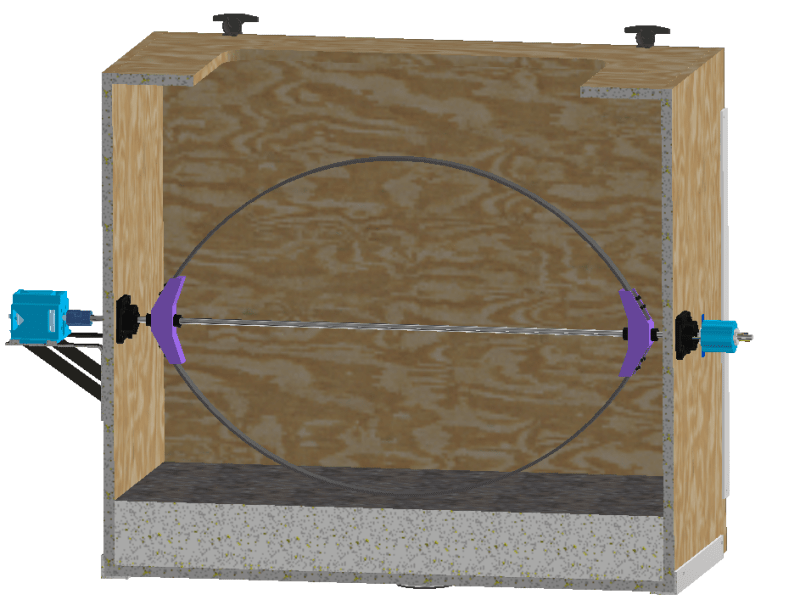
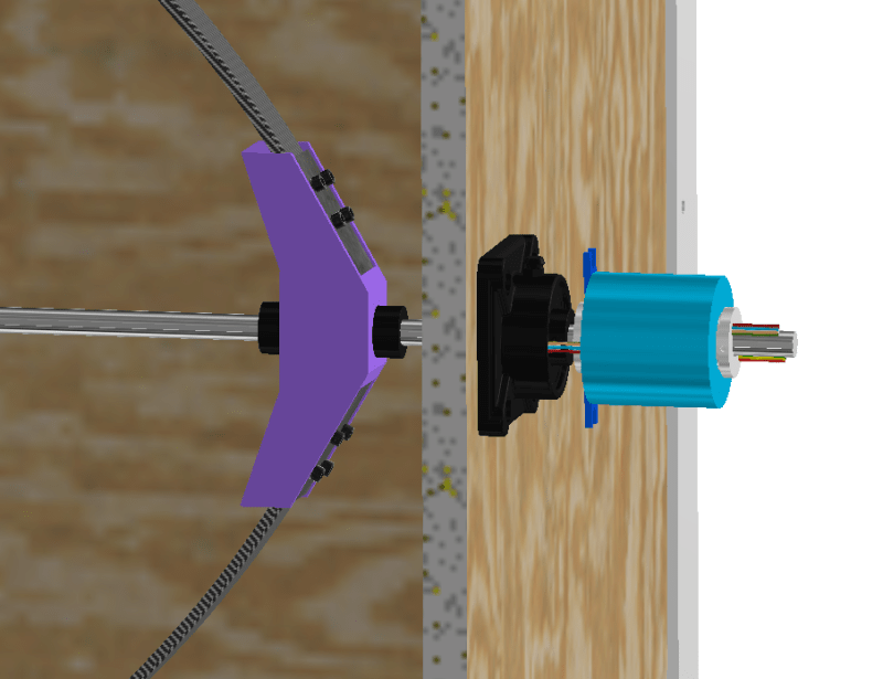
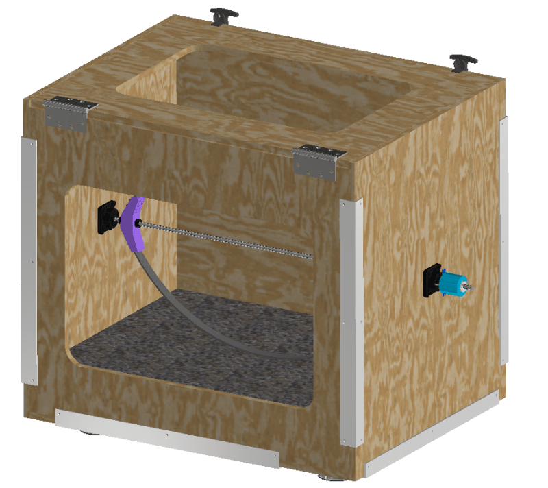
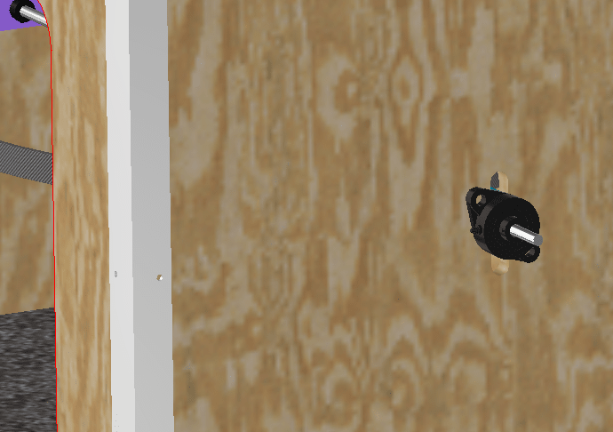
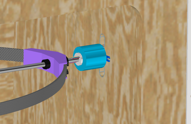
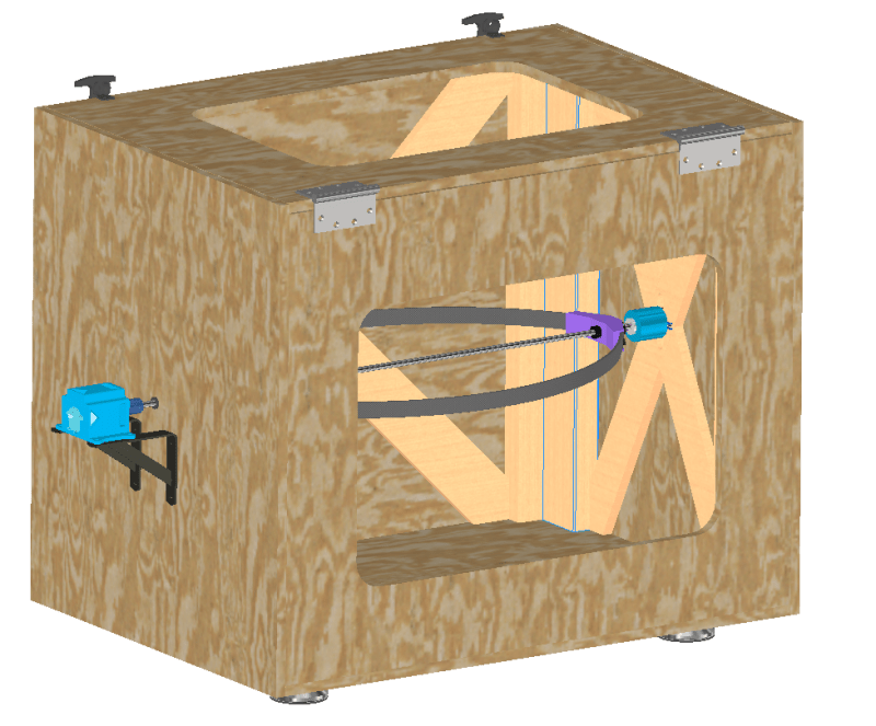
Hello, I am currently designing a test rig to test high speed carbon bows. I recently hit a snag when I was told to add a slip ring to the design. Anyone have any ideas or tips on how I should integrate this into the design? The slip rig has to withstand up to 4000rpm so I have selected the g012-12 Sereis. Pictures attached. Thank you!
2_uz82nk.png
3_adaarp.png
1_y29s4q.png
 
Replies continue below

Recommended for you

A flexible coupling between slip ring shaft and turning shaft, rigid body mount, and good alignment between shafts.

I'm not sure wood would work too well at 4000 RPM (natural frequencies?)
 
Thank you for your reply, I am trying to find what you mean by "flexible coupling". My greatest issue with mounting the slip ring on the outside was finding a way to rotate past the self aligning bearning. While I was working on this today I came up with this solution, what do you think? I put the slip ring inside the rig and cut a slot out of the box to allow wires to pass through. Also do you have any other suggestions besides wood? Thank you
5_lkfzl6.png
4_iqbun5.png
 
1) Is that a ball screw or acme screw going thru the box? And you want to rotate it at 4000 rpm? You didn't ask about this but I will comment anyway. Without some intermediate supports I think your screw (or shaft) will destroy itself at that speed from whiplash. I don't think you will ever get to 4000 rpm.

2) And, not asking you to reveal too much proprietary stuff here, but why the slip ring? Some electrical signals are going through there? Is the shaft hollow to allow conductors internally?

3) "I am trying to find what you mean by "flexible coupling" You already have one on the drive end. At least that's what it looks like between the motor and the shaft. You will need a flexible coupling on the slip ring only if it is hard mounted to some stationary surface. I would think you would want to mount it directly on the shaft and just restrict its rotation with some kind of flexible arm or strap. You need a flexible coupling whenever you have two hard-mounted and connected rotary devices. For example, the centerline of your shaft is determined by the position of your bearings. The position of the centerline of the motor is determined by its hard mount. You will do everything you can to get the motor centerline and shaft centerline exactly aligned. But it will never happen. Ever. That's why you need a flexible coupling. It transmits torque between two misaligned shafts.

4) Something better than wood? Aluminum. Maybe even plexiglas or lexan. Depends on how long this system should last and how much it will be used.
 
1) It is a keyed rotary shaft going through the center. I had some extra stock in the shop from the last similar test rig we made for this company. I will consider other options though.
2) The slip ring is going to be used to give data directly from the bow, it will be fastened directly to it.
3)I have the slip ring directly on the shaft with high profile set screws preventing it from turning. I will take a look at the flexible coupling more.
4) The problem with going better than wood is also budgeting. This test rig is not meant to last long term and will only be used for initial data testing.
 
My worry about wood is that it is not stiff enough. It will bend easy. The slip ring will need to stay in alignment to prevent its bearings from seeing large loads due to eccentricities or balance problems. I'd consider making the end sides that mount the bearings out of aluminum and maybe the bottom also. Wood for the rest may be o.k.
 
Seems like a perfect application for an extruded aluminum frame and bearing supports with acrylic sheets on the sides for safety. Check 8020.net. They have everything you need.
 
What if I did a combination of extruded aluminum frame and wood? I'm not sure how acrylic compares to wood price wise, but we are expecting catastrophic failure during testing, and I'm concerned how acrylic would take the impact compared to wood. The wood I am using is 3/4 inch thick, so I am hoping that will keep the damage somewhat contained.
 
I just think the bearings should be mounted on a more secure surface, especially if they are expected to withstand the forces generated by two bows spinning at 4000 rpm (which by the way I do not think it will attain). I think the impact resistance of acrylic is pretty good. A supplier could tell you more.

Is it important to see this device in operation?

Have you spun things like this that fast successfully in the past?
 
Yes another suggestion I received was to add cross beams on the side of the box for support near the bearings. We would like to record the bow spinning, so at least one window is required. We did have another rig spin up, but I am unsure how fast it went. I was not present at the company during that time.
 
I don't know about using the slip bearings as the main bearings. You'd have to look at the expected forces on those bearings (from run out and balance and natural frequencies) and compare to the ratings for the bearings.
 
I am not using the slip ring bearings as any sort of shaft alignment, I have two self aligning bearings on each end. I will be making another post regarding the mount shape soon as the slip ring is now sorted, thank you everyone.
 
Status
Not open for further replies.
Back
Top