Continue to Site

Eng-Tips is the largest engineering community on the Internet

Intelligent Work Forums for Engineering Professionals

  • Congratulations KootK on being selected by the Eng-Tips community for having the most helpful posts in the forums last week. Way to Go!

Sloping Roof with Flat Roof Members

Status
Not open for further replies.

Grant M

Structural
Jun 12, 2018
18
Hi all,

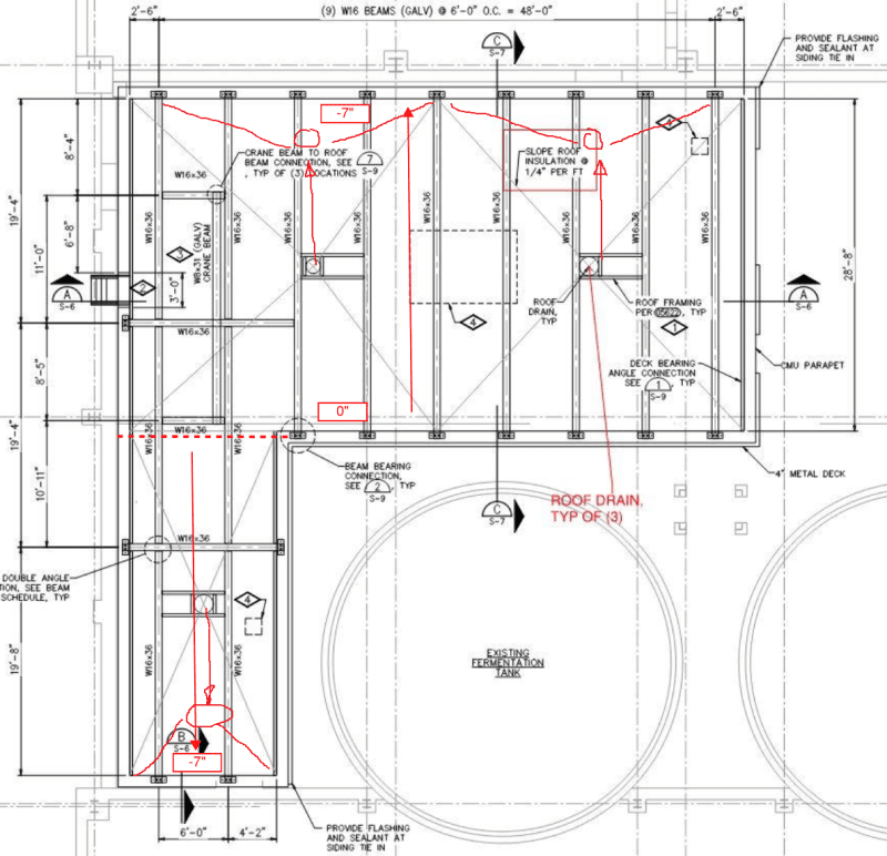
I am working on a project involving a new masonry building with a steel beam and metal deck roof system. My original design called for tapered roof insulation to achieve a 1/4"/ft roof slope to drains (see attachment of roof structure layout). The cost came back incredibly high, and the client wanted to look at having the roof beams/deck have the slope rather than the insulation.

Does anyone have any suggestions on how this could be achieved? Due to the "L" shape of the building, just dropping the beams at one end of the wall is not nearly very easy to achieve due to all the connecting elements/framing.

I appreciate the help!
 
 https://files.engineering.com/getfile.aspx?folder=6887cdff-7123-4519-9ccb-f7875174b472&file=Roof_Beam_Layout.JPG
Replies continue below

Recommended for you

This is commonly done in some parts of the world like Russia, but in my neck of the woods, everyone slopes the insulation/roofing. Anyway, I would just put the top of steel elevations of every beam and connection and let the steel detailer take care of the rest. The CMU itself can be cut and grouted to the proper elevation. It's not that complicated. The drains will have to be at one end instead of in the middle. If there's an architect or MEP engineer, they can advise if it needs two directions of slope. When I did it before, it just needed to be sloped in one axis, kind of like a monoslope roof but much flatter.

This is probably obvious, but I wouldn't slope the crane beam.
 
Yea I would lean on the architect to try to figure out a drainage scheme if you have one. You can play with TOS elevations , the arch can find a high point and ask for low points but just sloping the framing can only accomplish so much. Normally when the build up the insulation, they use compound slopes to direct the water to scuppers or gutter drains. Only adjusting 1 angle of the panel is not going to accomplish all of the water collection needed if you cannot slope to and drain off the face of a wall.
 
Thank you both for your ideas, we do not unfortunately have an architect working on this project (most of those responsibilities have fallen to me). I will try to work with the plumber to see if he has any input on the drainage direction/collection of storm water.

In your experiences, is there any issue with anchoring the steel beam (via baseplate) to the CMU wall when the members are sloped? Or would the beams be mitered at each end to keep the beam flat at the connection point?

Thanks again!
 
Short answer is no. Long answer, just not too much slope lol. The detail gets harder and harder the more slope but still doable even for steep roofs.

The beams should be mitered so that it presents a flat edge to the connection though.
 
Sounds good, based on my dimensions I should be able to just drop the beam connection by one course of CMU (8") to achieve the 1/4" slope we currently have.

Those beams connect into a bond beam which acts as part of the building diaphragm to distribute lateral loads into the shear walls, would you happen to know how to keep that bond beam continuous when the connections on either end are at different elevations?
 
Having only an 8" drop is ideal then for bond beam continuity. Have the contractor provide raked (sloped) side walls made out of a 2 course bond beam block, that is cut accordingly to match the slope. Then just tie the rebar on the slope as well to maintain continuity.
 
This might be unconventional and I haven't done it, but with your layout, you could technically slope the beams along two axes just by playing with top of steel elevations.
 
milkshakelake said:
This might be unconventional and I haven't done it, but with your layout, you could technically slope the beams along two axes just by playing with top of steel elevations.

I'm pretty sure the guys laying the deck would find your house and murder you in your sleep.
 
My first project at my current job, I had to do a compound roof slope achieved solely by adjusting the T/Steel elevations.

2 things in my favor:
1) the whole thing was steel framed, so no messing around with CMU and bond beams.
2) the architect made me do it. Maybe the deck erectors murdered him in his sleep.[sleeping]

Please note that is a "v" (as in Violin) not a "y".
 
Below is how I would look at doing this. In this case you would only need a few small crickets to divert the water to the drains. Crickets are nowhere near as costly as 3D roofing. Many other options as well, but that will depend on where the drains are. You will need a couple of connection details for the mono-rail.

roof-alt_vcineb.png
 
Thank you all I appreciate the help! I think that concept definitely makes the most sense considering the shape of the building Brad805, thanks for sharing.
 
Status
Not open for further replies.

Part and Inventory Search

Sponsor