Continue to Site

Eng-Tips is the largest engineering community on the Internet

Intelligent Work Forums for Engineering Professionals

  • Congratulations KootK on being selected by the Eng-Tips community for having the most helpful posts in the forums last week. Way to Go!

Slot True Position Tolerance Along Length 1

Status
Not open for further replies.

franhd

Mechanical
Aug 13, 2023
10
Hi all,

I understand how TP tolerances are distributed by the difference in MMCs in reference to Y14.5 appendix B (fixed fastener/floating fastener conditions).
When it comes to bidirectional tolerancing for slotted holes, I can speculate that you can apply those formulas to the narrow width of the slot.
How would you calculate your TP tolerance for its length? Every example online seems like the length is arbitrary.

I appreciate the responses.
 
Replies continue below

Recommended for you

Please link to the material that you feel is confusing.
 
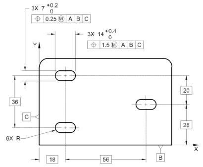
2021-06-23_195043_kj8g7m_cy2do2.jpg


In the above example, I can understand how the TP tolerance of .25 is calculated using fixed or float fastener formulas, if we pretend that the narrow width has the same diameter as if it was a regular clearance hole.
Where does 1.5 tolerance come from? It wouldn't be calculated as the difference between the slot's MMC and the fastener's.
 
What is missing is the mating part tolerances and function. Without that information it is only a guess.

Even with the fixed/floating formulas, the user is allocating tolerance between the two parts and the mutual fastener. It could all go one way or be evenly divided, but not knowing about all the parts no formula is certain to give a useful answer.

 
To add a dimension to the analysis - they may be slots to allow an amount of re-positioning in the slot direction. Unless one knows how much was allocated to that movement one cannot know how much remains.
 
@franhd, I think you may be looking at or attempting to evaluate this from the wrong perspective. For the fixed/floating fastener method to work, I believe you need to know about the mating part. Since we don't have the mating part (as far as I can tell), you can't apply the fixed or floating fastener formulae to this scenario. I think what you can do is calculate the virtual condition of the slots.

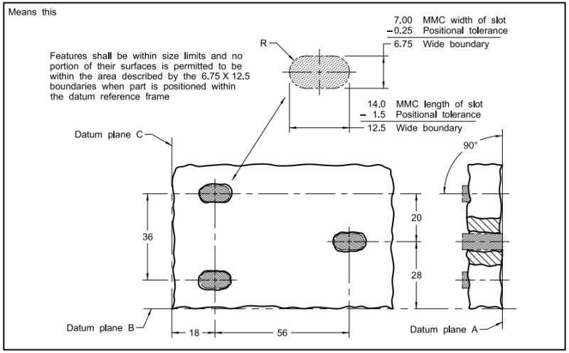
You posted figure 10-35 from ASME Y14.5-2018 and the continued figure shows the meaning of the callout. You can see that this results in a slot shaped inner boundary in which no element of the surface shall violate.

Fig10-35-cont-y14_5_mxnpxz.png


If you eventually do want to evaluate the fit of some mating part (for simplification assume the mating part has three circular fixed studs), you'll need to find the outer boundary of the studs and then evaluate the gaps between the slots' inner boundary and the studs' outer boundary to determine one of the worst case fits (another worst case may exist with the outer boundaries of the slots and inner boundaries of the studs).

As @3DDave indicated, slots are often used to allow an amount of repositioning in the slot direction. Your evaluation may show that under a worst-case condition, you only get so much room for free adjustment in the slots.

I know from experience we've had some parts with slots to allow for adjustment, but then the assembled parts get together and one of the studs or bolts hits the end of the slot and doesn't allow for complete assembly of say the hose or tubing to the item mounted to the bracket. It can be quite frustrating.
 
Status
Not open for further replies.

Part and Inventory Search

Sponsor